Hand-held oscillatory power tool with two-axis tool mounting

Inactive Publication Date: 2011-09-01
C ENTERPRISE HK
View PDF11 Cites 72 Cited by
  • Summary
  • Abstract
  • Description
  • Claims
  • Application Information

AI Technical Summary

Benefits of technology

[0041]This invention provides a power tool which can be effectively and efficiently used with the axis of rotation of the chuck oriented at different angles to the housing, allowing an ergonomically optimum gripping position to be maintained by the user, indepen

Problems solved by technology

Many prior designs proved to be either too complicated to mass produce o

Method used


Image

  • Hand-held oscillatory power tool with two-axis tool mounting
  • Hand-held oscillatory power tool with two-axis tool mounting
  • Hand-held oscillatory power tool with two-axis tool mounting

Examples


Embodiment Construction

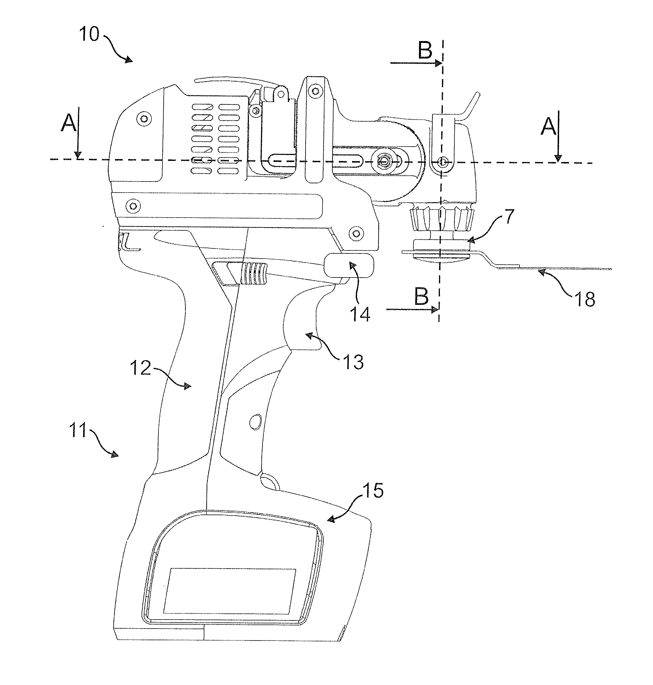
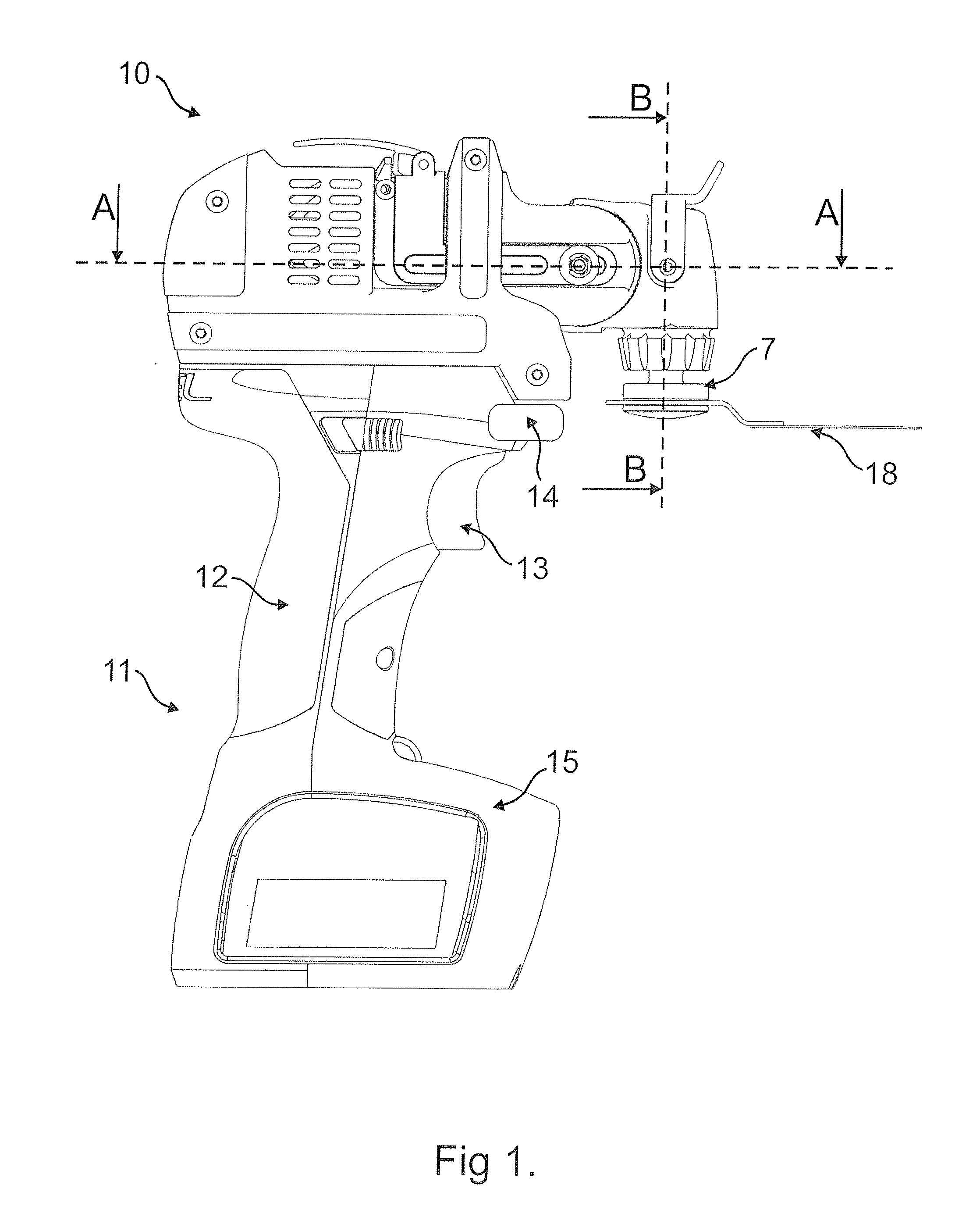
[0052]Referring to FIG. 1 a hand tool according to an embodiment of the invention includes a modular tool body 10 and a handle assembly 11, from which the tool body 10 can be demounted. The handle assembly 11 includes a hand-grip portion 12, a trigger 13, a control button 14 and a battery pack portion 15. Electrical contact pairs (not shown) at the interface between the tool body 10 and handle assembly 11 are mutually engaged when the two parts are connected, as shown in FIG. 1, allowing power to be supplied from batteries (not shown) in the battery pack portion 15 to a rotary electric motor 16 (FIG. 3) disposed in the tool body 10. The motor 15 powers an oscillatory drive, described in more detail below, to oscillate a chuck 17 and an attached tool 18. The tool 18 shown is a blade but many alternative coarse or fine cutting tools, such as sanding, grinding, polishing tools, or the like, may be held in the chuck 17

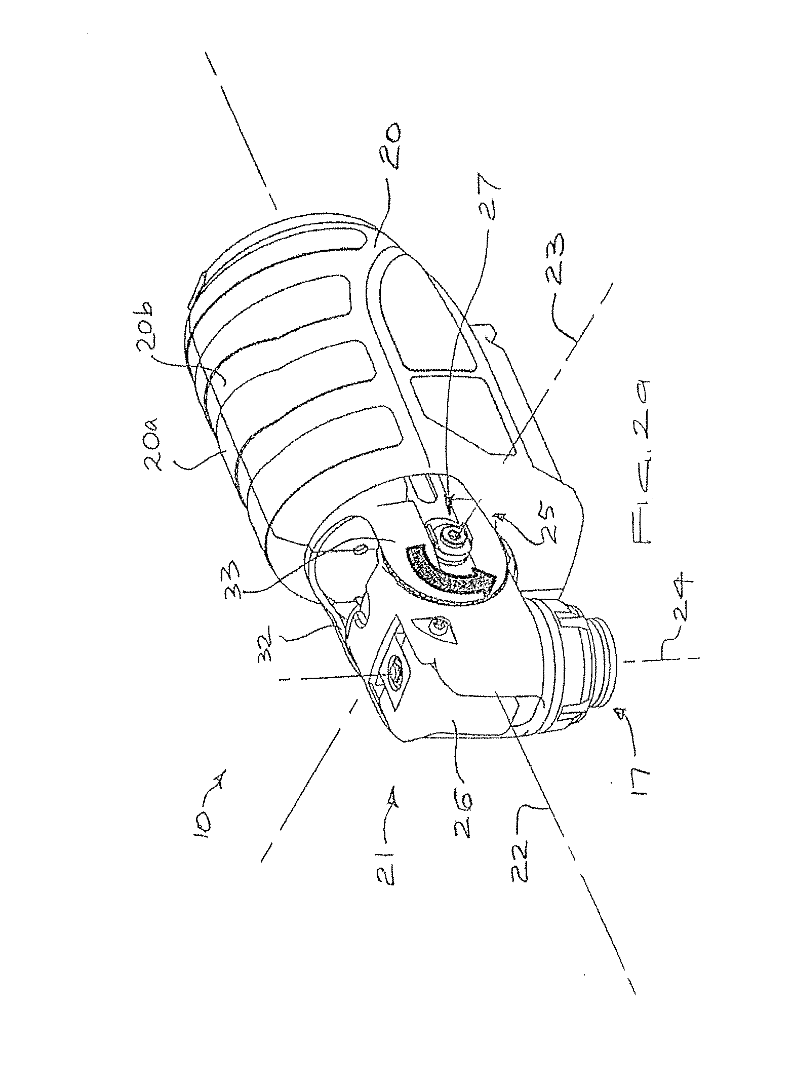
[0053]FIGS. 2a-2c show that the tool body 10 comprises a housing 20 t...


PUM

PropertyMeasurementUnit
Forceaaaaaaaaaa
Areaaaaaaaaaaa
Torqueaaaaaaaaaa

Abstract

A hand-held power tool includes a motor mounted in a housing, with a two-axis universal joint mounted to the housing and supporting a rotary chuck. The universal joint includes a yoke mounted to the housing and a hub mounted to the yoke, the hub supporting the chuck. First and second clutches are provided for locking the yoke and the hub. A locking mechanism operatively connects the first and second clutches, and releases both of the first and second clutches simultaneously. A quick release chuck includes a spindle having a longitudinal bore for accepting a shank. A ball or like engaging device is disposed in a radial bore, extending into the longitudinal bore, and radially movable so that at least a portion of the ball extends radially into the longitudinal bore to engage a recess in the shank. A spring biased outer collar disposed about the spindle is movable longitudinally relative to the spindle and has a tapered face for forcing the ball into an aperture. A spring biases the collar into a locking position.

Description

TECHNICAL FIELD[0001]The present invention relates to hand-held power tools, particularly multi-purpose power tools.BACKGROUND OF THE INVENTION[0002]Various hand-held oscillatory power tools are useful for performing cutting operations, such as sawing, sanding, grinding, and polishing. Particularly for fine work, and when the tool is being used for an extended time, physical stresses can result and the ergonomic features of the tool are very important. It will be understood that there is a need for a power tool which reduces the physical stress that can occur using prior art tools.[0003]Various quick release chucks are known in the art for holding tools or bits. Many prior designs proved to be either too complicated to mass produce on a commercial basis, or simply did not provide satisfactory performance. Accordingly, an uncomplicated and easy to produce quick release chuck which affords quick and easy change-out of saw blades without degrading the reliability or safety of the tool ...

Claims


Application Information

Patent Timeline
IPC IPC(8): B25F5/00B25F5/02B23B31/107
CPCB23B31/1071Y10T279/17811B27B19/006
Inventor ELSWORTHY, CHRISTOPHER THOMAS
Owner C ENTERPRISE HK
Why Eureka
Try Eureka