
High energy density ionic dielectric materials and devices

a dielectric material and high energy density technology, applied in the direction of inorganic insulators, fuel cells, conductive materials, etc., can solve the problems of limited capacitive energy density, limited operating voltage of these dielectrics, limited energy storage capacity of these dielectrics, etc., and achieve the effect of effective capacitan

Inactive Publication Date: 2011-09-01
RECAPPING +1
View PDF6 Cites 25 Cited by
  • Summary
  • Abstract
  • Description
  • Claims
  • Application Information

AI Technical Summary

Benefits of technology

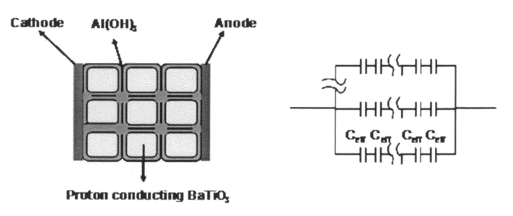
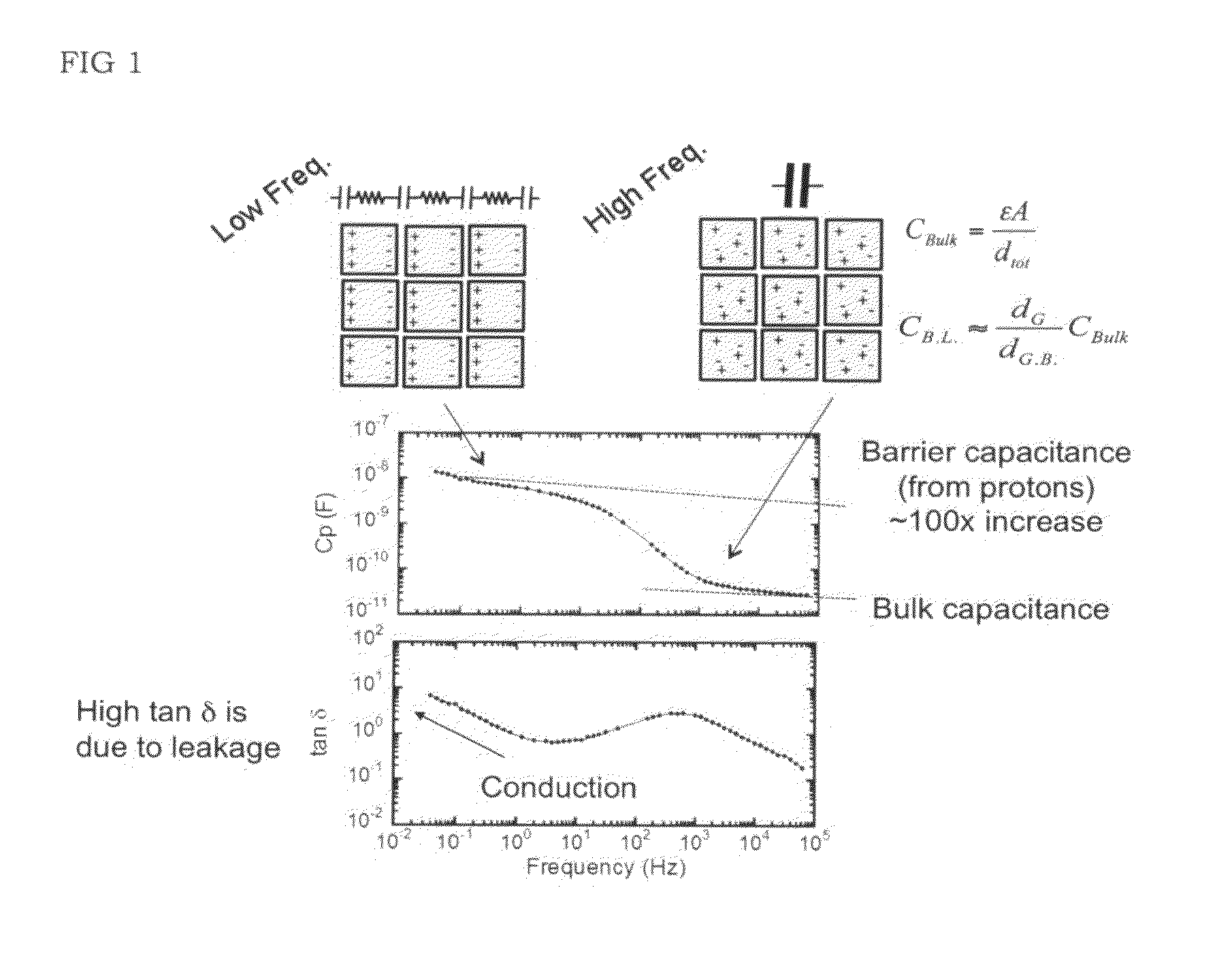
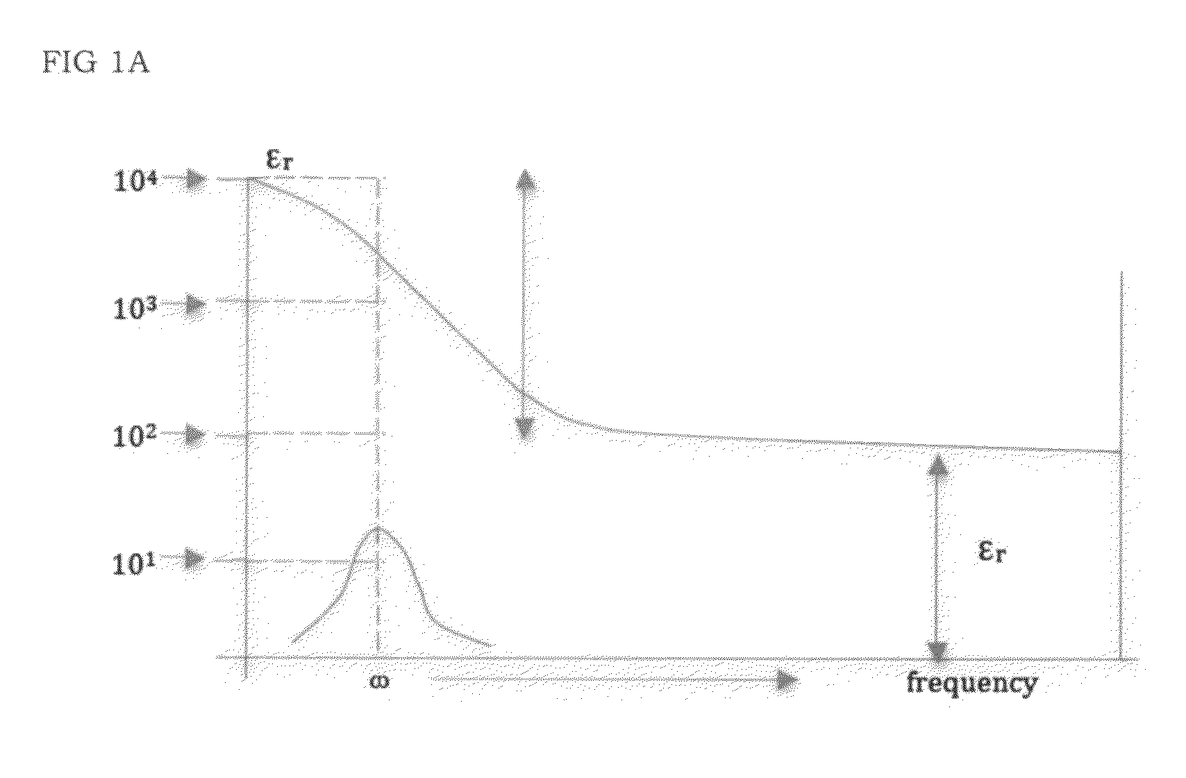
[0043]An IBBL effect such as PBBL effect may be generated by transport of ions such as protons under an electric field to accumulate at resistive grain boundaries to yield an effective capacitance shown schematically in FIG. 1. The relaxation process shown in FIG. 1 relates to accumulation of protons at grain boundaries by proton transport under bias. In contrast, effective capacitance in a polycrystalline ceramic that utilizes electrons and holes as the primary charge carriers is typically manifested by higher frequency relaxations of about 105 Hz in BaTiO3 based materials and about 106 Hz in SrTiO3 based material. An IBBL effect such as PBBL effect may be measured by known techniques such as impedance spectroscopy, cyclic voltammetry, galvanostatic charge / discharge, polarization-field (charging and discharging), leakage current measurements, and dielectric breakdown strength at temperature over a range of about −50° C. to about 65° C.
[0044]The energy storage potential of energy storage devices that employ ionically conducting materials that may show an IBBL effect such as a PBBL effect may be controlled by varying the grain composition, grain boundary morphology and grain size of the dielectric grains. The grain composition may be controlled by varying the concentration of acceptor dopants, and / or by incorporating one or more minority dopants such as electron acceptor species such as but not limited to Mn, Cr, Fe, Ni, and donor species such as but not limited to Nb, La, Y, Dy, and Nd.
[0045]Where the ionically conducting material is a Li+ type conducting material such as any one or more of (Li,La)TiO3, LiCoO4 and LiMn2O4, the grain composition may be controlled by varying the concentration of acceptor dopants such as electron acceptor species such as but not limited to Sc, Cr, Mn, Fe, Ca, Ni, Cu, Zn, on B-site and donor species such as but not limited to Mg, Ca, Sr, on A-site or Nb, Ta, Mo, W, Re, Sb, on B-site.
[0046]Where the ionically conducting material is a Ag+ conducting material rubidium silver iodide type compound type material, the grain composition may be controlled by varying the concentration of acceptor dopants such as electron acceptor species such as but not limited to O, Se, S, Te and combinations thereof, in substitution for I, and donor species such as but not limited to Be, Mg, Ca, Sr, Ba, Sc, in place of Ag or Rb and combinations thereof.
[0047]Where the ionically conducting material is a Na+ type material such as Na2S, the grain composition may be controlled by varying the concentration of acceptor dopants such as electron acceptor species such as but not limited to N, P, As, Sb, C, Si and combinations thereof and donor species such as but not limited to Be, Mg, Ca Sr, and combinations thereof;
[0048]Where the ionically conducting material is a O−2 type material, such as Bi2(Cu0.1V0.9)O5.35, the grain composition may be controlled by varying the concentration of acceptor dopants such as electron acceptor species such as but not limited to Mn, Ni, Zn, Sc, Ti, V, Cr, La, Nd, Dy, Ho and combinations thereof and donor species such as but not limited to Nb, Ta, W, Mo, and combinations thereof.

Problems solved by technology

The operating voltage of these dielectrics, however, is limited by electric field drop across grain boundaries as well as by tunneling of electrons across grain boundaries.
This, in turn, limits the capacitive energy density that can be achieved.
The energy storage capacity of these dielectrics however, is limited by electron tunneling at the grain boundaries under high electric fields.
Also, typical barrier layer dielectrics are only able to withstand low voltages of about 3 Volts.

Method used


Image

  • High energy density ionic dielectric materials and devices
  • High energy density ionic dielectric materials and devices
  • High energy density ionic dielectric materials and devices

Examples


example 1a

Manufacture of Protonated Ba(Sc0.1Ti0.9)O3

[0079]197.3 gms of BaCO3, 71.88 gms TiO2 and 6.896 gms Sc2O3 starting materials, where the starting materials have a purity of 99.9% or more from Sigma-Aldrich, are ball milled in a Teflon lined ball mill with yttria-stabilized-zirconia balls in ethanol for 24 hrs to form a slurry.

[0080]The slurry is dried at 80° C. for 24 hrs to produce a dried powder. The dried powder is successively calcined at 1050° C. for 10 hrs, at 1150° C. for 10 hrs, at 1250° C. for 10 hrs, at 1400° C. for 10 hrs, and then at 1500° C. for 10 hrs to form Ba(Sc0.1Ti0.9)O2.95(VO)0.05 where VO is oxygen site vacancy. The Ba(Sc0.1Ti0.9)O2.95(VO)0.05 is ball-milled in ethanol for 24 hrs with yttria-stabilized zirconia balls to form a slurry of milled powder that has a particle size of 1 micron or less. The milled powder is dried at 80° C. and then uniaxially pressed at 15,000 PSI to produce a preform. The preform then is isostatically compressed at 30,000 PSI. The resulti...

example 1b

Manufacture of Protonated Ba(Sc0.4Ti0.6)O3

[0084]The procedure of example 1A is followed except that 197.3 gms BaCO3, 47.92 gms TiO2 and 27.584 gms of Sc2O3 are employed.

EXAMPLE 1BT

Manufacture of Ba(Sc0.4Ti0.6)O2.83(Vo)0.17(H*)0.06

[0085]The sintered disk produced as in example 1B is exposed to steam flowing at 0.001 CFM in a tube furnace at 560 PSI during cooling from 900° C. to 200° C. at a rate of 0.5° C. / min.

EXAMPLE 1BU

Manufacture of Ba(Sc0.4Ti0.6)O2.82(Vo)0.18(H*)0.04

[0086]The sintered disk produced as in example 1B is exposed to steam flowing at 0.001 CFM in a tube furnace at 560 PSI during cooling from 900° C. to 300° C. at a rate of 0.5° C. / min.

example 1c

Manufacture of Protonated Ca(Sc0.1Ti0.9)O3

[0087]The procedure of Example 1A is followed except that BaCO3 is replaced with 100.08 gms CaCO3.

EXAMPLE 1CT

Manufacture of Ca(Sc0.1Ti0.9)O2.9575(Vo)0.0425(H*)0.015

[0088]The procedure of example 1C is followed except that the sintered disk produced as in example 1C is exposed to steam flowing at 0.001 CFM in a tube furnace at 1000 PSI during a slow cool from 900° C. to 200° C. at a rate of 0.1° C. / min.


PUM

PropertyMeasurementUnit
temperatureaaaaaaaaaa
relative permittivitiesaaaaaaaaaa
voltagesaaaaaaaaaa

Abstract

Dielectric compositions that include compound of the formula [(M′)1−x(A′)x][(M″)1−y−z,(B″)y(C″)z]O3−δ(VO)δ and protonated dielectric compositions that include a protonated dielectric compound within the formula [(M′)1−x(A′)x](M″)1−y−z(B″)y(C″)z]O3−δ+h(Vo)δ(H*)2h are disclosed. Composite materials that employ one or more of these dielectric compounds together with an electrolyte also are disclosed. Composite material that employs one or more of these dielectric compounds together with an electrochemally active material also are disclosed.

Description

REFERENCE TO RELATED APPLICATIONS[0001]This application claims priority to U.S. Provisional Application 61 / 278,867 filed Oct. 13, 2009 and to U.S. Provisional Application 61 / 303,644 filed Feb. 11, 2010, the teachings of which are incorporated herein by reference in their entirety.BACKGROUND OF THE INVENTION[0002]In traditional barrier layer, polycrystalline dielectrics, electrons are the mobile species. Use of electrons as the mobile species enables these dielectrics to achieve relatively high frequency response. The operating voltage of these dielectrics, however, is limited by electric field drop across grain boundaries as well as by tunneling of electrons across grain boundaries. This, in turn, limits the capacitive energy density that can be achieved.[0003]Typical barrier layer dielectrics provide effective relative permittivities of about 20,000 to 100,000. The energy storage capacity of these dielectrics however, is limited by electron tunneling at the grain boundaries under h...

Claims


Application Information

Patent Timeline
Patent Type & Authority Applications(United States)
IPC IPC(8): C04B35/468C04B35/465C04B35/472C04B35/46H01M8/10H01B1/02H01B1/00H01M4/86H01G9/022C04B35/64
CPCC01G23/002Y02E60/525C01G25/006C01G31/006C01G45/006C01G49/009C01G51/006C01G51/40C01G53/006C01G53/40C01G55/002C01P2002/34C01P2002/52C01P2002/54C01P2004/61C01P2004/62C01P2006/40C04B35/465C04B35/4682C04B35/472C04B35/486C04B35/49C04B35/491C04B35/495C04B35/6262C04B35/62675C04B2235/3201C04B2235/3203C04B2235/3208C04B2235/3215C04B2235/3224C04B2235/3225C04B2235/3251C04B2235/3258C04B2235/3284C04B2235/3298C04B2235/5445C04B2235/656C04B2235/6588C04B2235/662C04B2235/76C04B2235/768H01B3/10H01B3/12H01M8/1246H01M10/0562Y02E60/521C01G23/006C01G23/003Y02E60/10Y02E60/50Y02P70/50
Inventor RANDALL, CLIVE A.CROSS, LESLIE E.YANG, ARAMDONNELLY, NIALL J.RAJAGOPALAN, RAMAKRISHNANBAKER, AMANDA LOU
Owner RECAPPING
Learn More