System and method for solar energy capture and related method of manufacturing

a solar energy and manufacturing technology, applied in the field of solar energy systems, can solve the problems of high efficiency pv cells, inefficient stationary solar concentration devices, and high cost of pv cells, and achieve the effect of higher efficiency

Active Publication Date: 2011-09-22
RGT UNIV OF CALIFORNIA
View PDF24 Cites 105 Cited by
  • Summary
  • Abstract
  • Description
  • Claims
  • Application Information

AI Technical Summary

Benefits of technology

The present inventors have recognized the desirability solar energy systems employing PV cells in addition to solar concentrators, and further recognized that existing systems employing fluorescent solar concentrators (FSCs) are advantageous in that, insofar as they employ slab waveguides, such systems can be more compact than many other forms of solar energy systems that employ other forms of solar concentrators. Additionally, however, the inventors have further recognized that a new form of solar energy system employing slab waveguides can be achieved having higher efficiency than existing systems if, instead of employing FSCs, the solar concentrators instead are built by placing a lens array adjacent to a slab waveguide formed between a low index cladding layer and an additional layer having prism facets, with the lens array being along the cladding layer opposite the additional layer of the slab waveguide having the prism facets. By appropriate design of the prism facets, total internal reflection can be achieved within the slab waveguide with respect to much if not all incoming light directed into the slab waveguide, and this light can in turn be directed to one or more PV cells positioned at one more ends / edges of the slab waveguide.
Additionally, the present inventors have also recognized the desirability of solar energy systems that are capable of receiving light from changing angles of incidence. Consequently, while prism facets with constant optical properties can be employed in at least some embodiments of the present invention, the present inventors have further recognized that in at least some other embodiments of the present invention the prism facets can be formed or revealed by way of one or more materials and / or processes that allow for the prism facet characteristics to vary, including location relative to the microlens, depending upon the light incident upon those prism facets. Also, in at least some other embodiments, components of the solar energy systems can be shifted slightly in various manners to also allow light of various angles of incidence to be received and directed to PV cells. In some such embodiments, the waveguide with the prism facets can he shifted relative to one or more lens devices. Further, the present inventors have also recognized the desirability of increasing the degree to which light is concentrated onto less numbers of (or smaller) PV cells, as well as the desirability of being able to receive multiple light components rather than merely a single light component or single range of light components, and have further developed various arrangements that facilitate achieving such objectives.

Problems solved by technology

While much effort is being focused upon developing more efficient photovoltaic (PV) cells that can generate ever greater amounts of electrical energy based upon a given amount of solar radiation directed upon those cells, high efficiency PV cells nevertheless remain expensive.
While potentially providing such advantages, existing solar energy systems employing both PV cell(s) and solar concentration devices have certain disadvantages as well.
In particular, some stationary solar concentration devices tend to be not very efficient.
While a fraction of the emitted fluorescence is trapped within the slab, and guided to an edge of the waveguide for illumination of a PV cell, a large fraction of the fluorescent light is re-absorbed and re-emitted into a non-guided direction, thus resulting in substantial inefficiency.
An additional problem associated with some conventional solar concentrators (e.g., imaging lens or minor-based concentrators) is that, for proper operation, such solar concentrators require sunlight that is incident from a particular direction relative to the concentrator.
Although it is possible to achieve such alignment by way of an “active” system that uses tracking (with or without positional feedback, such active systems are expensive and often complicated to implement.
Still another disadvantage associated with at least some conventional solar energy systems employing solar concentrators is that they are complicated and / or expensive to manufacture.

Method used


Image

  • System and method for solar energy capture and related method of manufacturing
  • System and method for solar energy capture and related method of manufacturing
  • System and method for solar energy capture and related method of manufacturing

Examples


Embodiment Construction

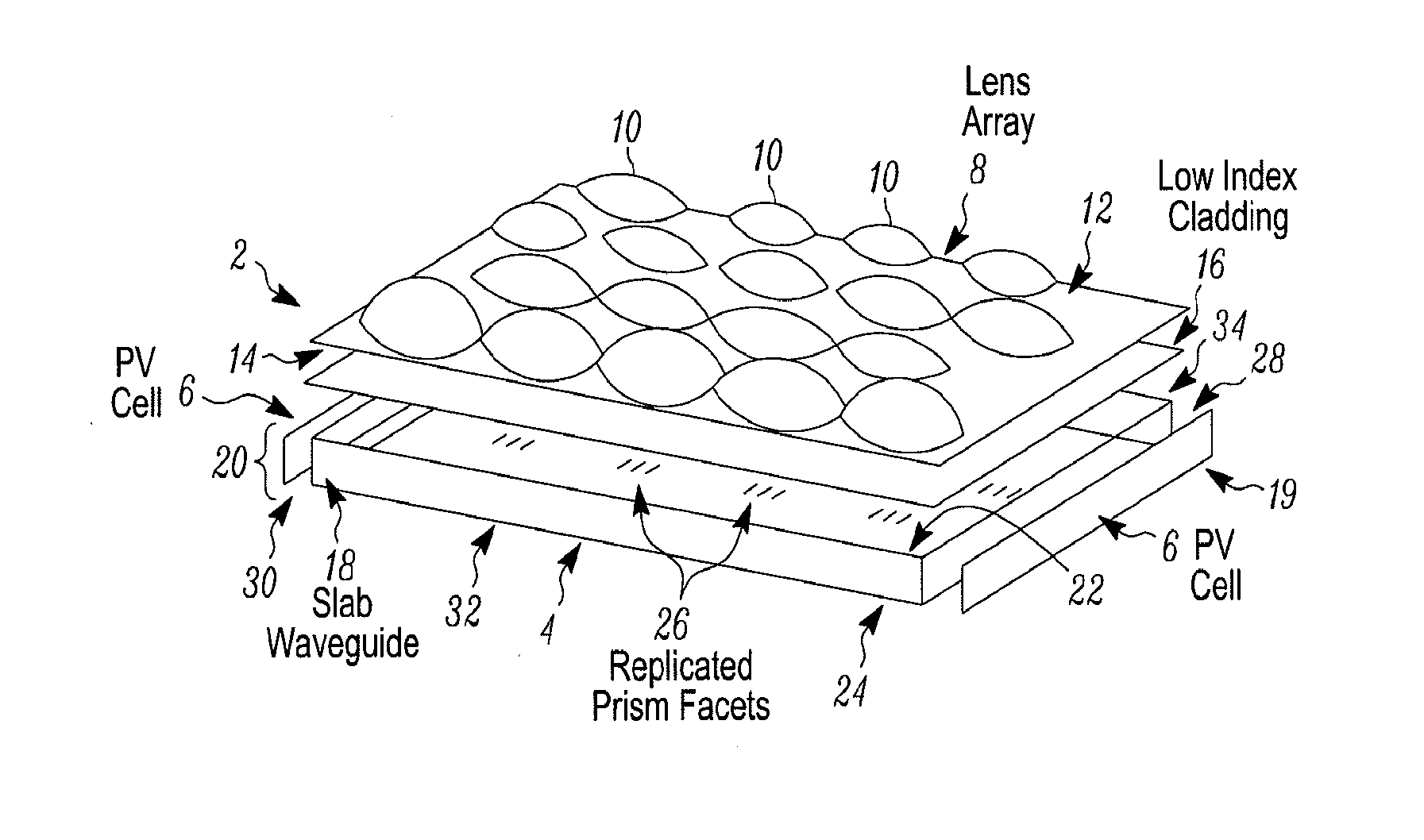
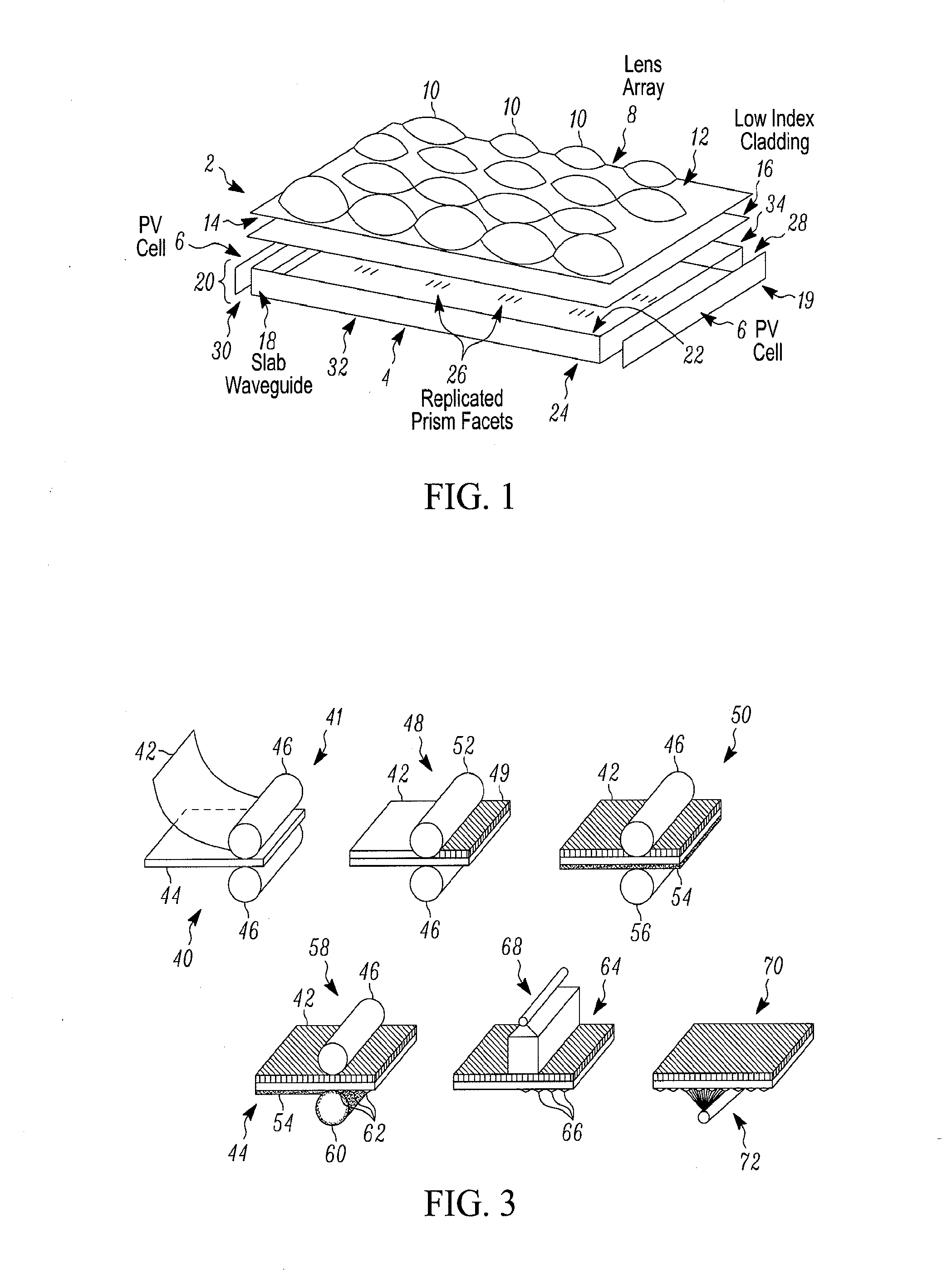
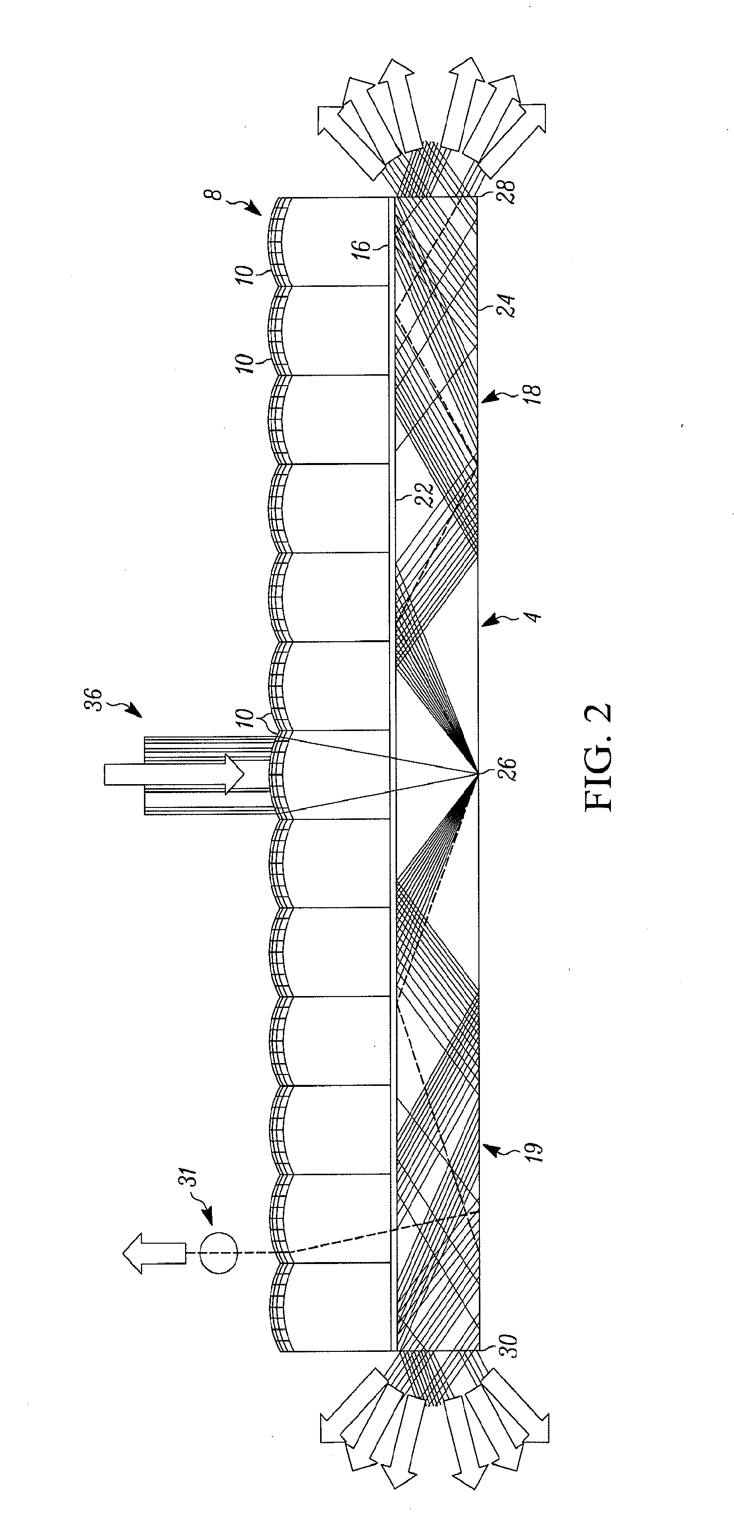
Referring to FIG. 1, an exploded view of a solar energy system 2 in accordance with one embodiment of the present invention is provided. As shown, the solar energy system 2 includes a solar concentration section 4 and multiple PV cells 6. The solar concentration section 4 can also be referred to as a micro-optic concentration section in view of the small size of the structure and its components relative to the overall physical structure of the system 2. More particularly as shown, the solar concentration section 4 includes a lens array 8 having multiple lenses 10 arranged substantially along a plane. The lenses 10, which in the present embodiment are formed by embossing the lenses on a surface of glass or plastic superstrate, can be referred to as microlenses, again in view of their size relative to the overall physical structure of the system 2. Sunlight (or possibly other incoming light) is incident upon an outer surface 12 of the lens array 8, and exits the lens array by way of a...


PUM

PropertyMeasurementUnit
angleaaaaaaaaaa
angleaaaaaaaaaa
angleaaaaaaaaaa

Abstract

A system and method of capturing solar energy, and related method of manufacturing, are disclosed. In at least one embodiment, the system includes a first lens array having a plurality of lenses, and a first waveguide component adjacent to the lens array, where the waveguide component receives light, and where the waveguide component includes an array of prism / mirrored facets arranged along at least one surface of the waveguide component. The system further includes at least one photovoltaic cell positioned so as to receive at least a portion of the light that is directed out of the waveguide. A least some of the light passing into the waveguide component is restricted from leaving the waveguide component upon being reflected by at least one of the prism / mirrored facets, hereby the at least some light restricted from leaving the waveguide component is directed by the waveguide toward the at least one photovoltaic cell.

Description

STATEMENT REGARDING FEDERALLY SPONSORED RESEARCH OR DEVELOPMENTField of the Invention The present invention relates to solar energy systems, and methods and, more particularly, to systems and methods for capturing solar energy that operate at least in part by way of concentrating received light prior to conversion of the light into electrical or other power, as well as to methods of manufacturing such systems.Background of the Invention Solar energy systems are of greatly increased interest due to rising energy demands worldwide and consequent rising prices for existing energy resources, especially petroleum resources. While much effort is being focused upon developing more efficient photovoltaic (PV) cells that can generate ever greater amounts of electrical energy based upon a given amount of solar radiation directed upon those cells, high efficiency PV cells nevertheless remain expensive. A less-expensive alternative to employing high efficiency PV cells is to employ low (or lowe...

Claims


Application Information

Patent Timeline
Patent Type & Authority Applications(United States)
IPC IPC(8): H01L31/0232H01L31/18F24S23/00F24S23/30
CPCF24J2/067F24J2/085G02B3/0056G02B6/0038G02B6/0053H01L31/0547Y02B10/12Y02B10/20Y02E10/43Y02E10/52H01L31/0543G02B6/0078F24S23/12F24S23/31Y02E10/47Y02B10/10H01L31/055Y02E10/40B29D11/00009B29D11/00865G01S3/7861G02B3/0037G02B6/26G02B7/005G02B19/0028G02B19/0042
Inventor FORD, JOSEPH E.KARP, JASON HARRISTREMBLAY, ERICHALLAS, JUSTIN MATTHEW
Owner RGT UNIV OF CALIFORNIA
Why Eureka
Try Eureka