Current sensor

a current sensor and current sensor technology, applied in the field of current sensor, can solve the problems of large offset output likely to be generated, large variation in connection resistance likely to occur, and difficulty in adjusting the balance between four magneto-resistive elements, etc., and achieve the effect of more effective application

Active Publication Date: 2011-09-22
TDK CORPARATION
View PDF10 Cites 52 Cited by
  • Summary
  • Abstract
  • Description
  • Claims
  • Application Information

AI Technical Summary

Benefits of technology

[0013]According to the first current sensor and the second current sensor, based on the compensation current generated by a potential difference between the first junction and the second junction in response to application of voltage between the third and fourth junction, or based on the compensation current depending on a difference between voltage drops generated in the magneto-resistive elements, a compensation current is provided for applying, to the magneto-resistive elements, the compensation magnetic field in a direction opposite to the induced magnetic field. Therefore, a variation in the characteristics between the magneto-resistive elements or variation in the connection resistance, or change in an output voltage caused by a temperature distribution is canceled. In addition, each the line portions of the compensation current line overlaps each of the magneto-resistive elements in the thickness direction, and has a width smaller than that of the magneto-resistive element. Therefore the maximum intensity and the average intensity of the effective magnetic field out of the compensation magnetic field, which are actually applied to the magneto-resistive elements, are improved and the resistance change amount of the magneto-resistive elements to the constant change amount of the compensation current is increased.
[0014]In the first and the second current sensors, the intensity of t

Problems solved by technology

However, in the case where a Wheatstone bridge is configured by using a magneto-resistive element with high impedance and high sensitivity, a large offset output is likely to be generat

Method used


Image

  • Current sensor
  • Current sensor
  • Current sensor

Examples


first embodiment

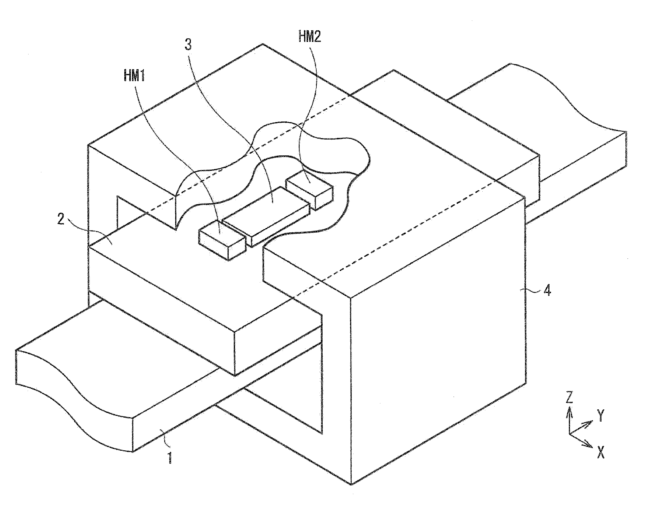
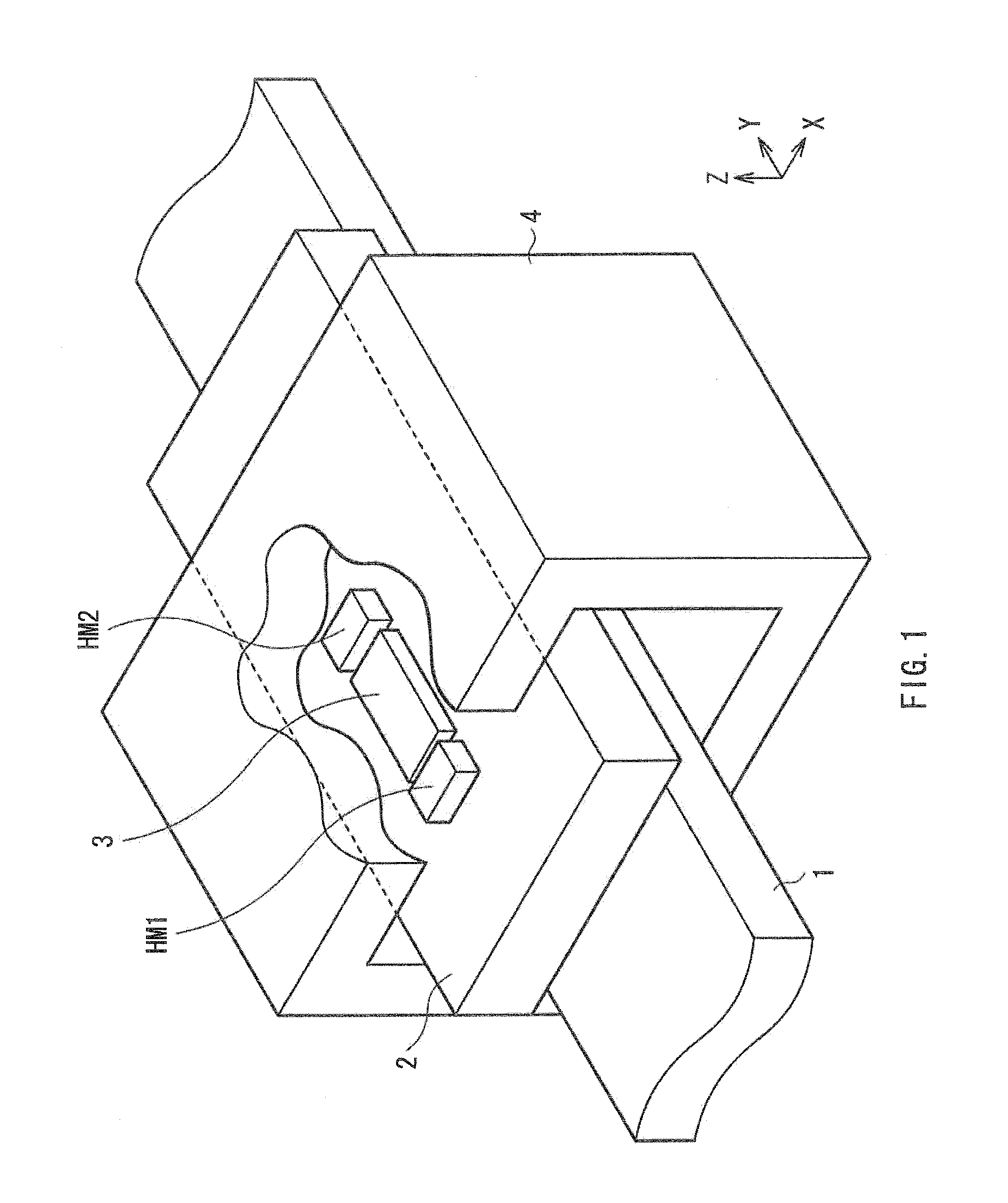
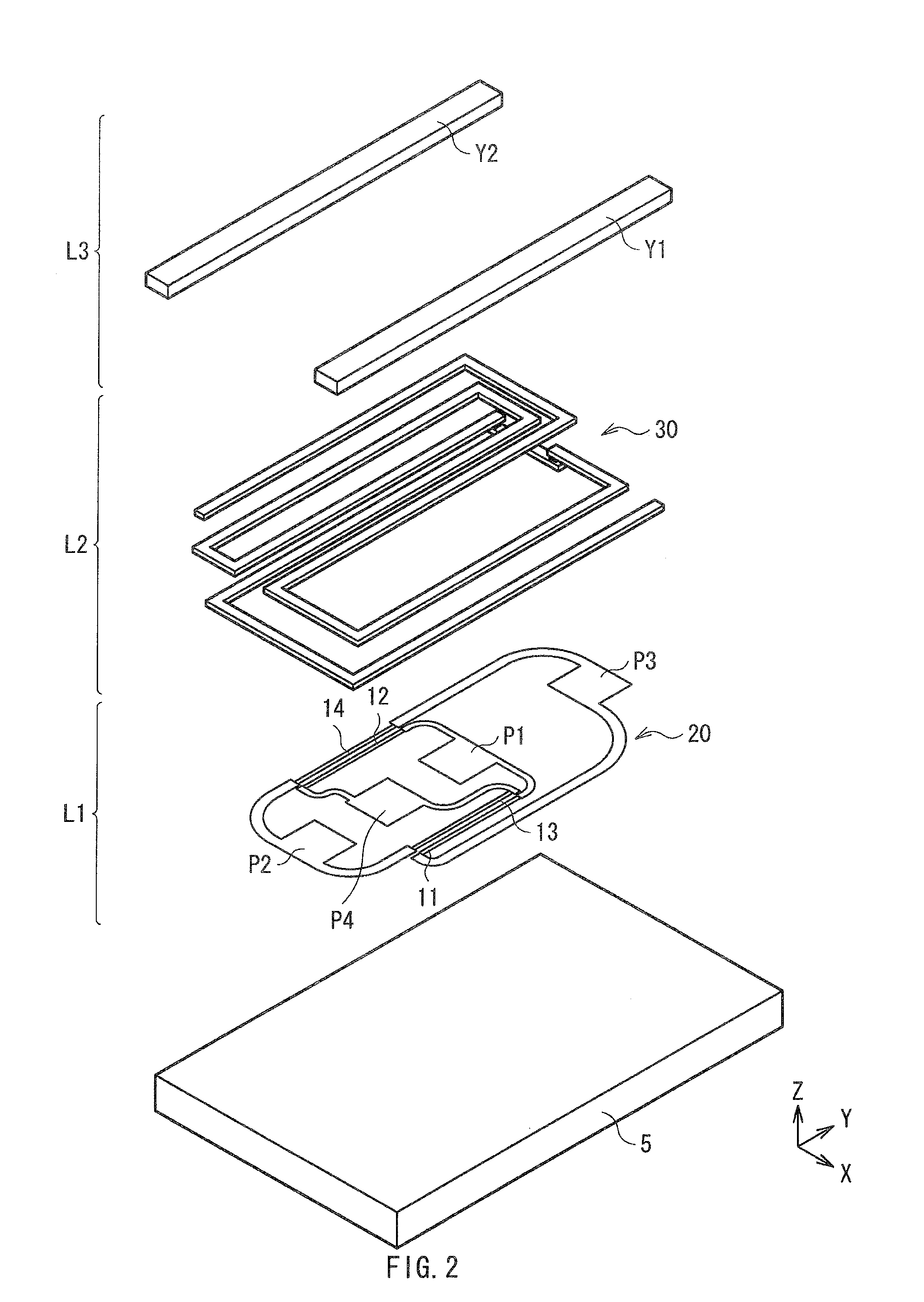
[0043]First, there is described a configuration of a current sensor as a first embodiment of the invention referring to FIG. 1 to FIG. 4. FIG. 1 is a perspective view illustrating a whole configuration of the current sensor according to the embodiment. FIG. 2 is an exploded perspective view illustrating a configuration of a sensor unit 3 which is a main part of the current sensor. FIG. 3 is a perspective view illustrating a detailed configuration of a compensation current line 30 of the sensor unit 3. Further, FIG. 4 is a sectional view of the sensor unit 3 taken along a IV-IV line of FIG. 3.

[0044]As illustrated in FIG. 1, the current sensor includes a straight conductor 1 through which a current-to-be-detected Im (described later) flows, a substrate 2 disposed in the vicinity of the conductor 1, and the sensor unit 3 disposed on the substrate 2. On the substrate 2, a pair of permanent magnets HM1 and HM2 is mounted so as to sandwich the sensor unit 3 along an extending direction (h...

second embodiment

Modification of Second Embodiment

[0078]In addition, in the embodiment, as illustrated in FIG. 13B, a pair of the line portions 31A and 31B is arranged so as to sandwich the GMR element 11 in the thickness direction. In this case, the pair of the line portions 31A and 31B is preferably provided on the respective sides of the GMR element 11 so that the centers of the line portions 31A and 31B sandwich the center of the GMR element 11. This is because the GMR element 11 is applied with the effective magnetic field which is more homogenized in the width direction. In this case, as illustrated in FIG. 13C, for example, while the pair of the line portions 31A and 31B is arranged at the positions with the equivalent distance from the GMR element 11 in the thickness direction, the widths W31A and W31B of the line portions 31A and 31B may be extended. In other words, the pair of the line portions 31A and 31B has a positional relationship of overlapping portions with each other in the thickne...

third embodiment

[0081]Next, a current sensor as a third embodiment of the invention will be described referring to FIGS. 16 to 19. In this embodiment, like reference numerals are utilized to indicate like components of the first embodiment described above, and the description thereof is appropriately omitted. FIG. 16 is a perspective view illustrating a whole configuration of a current sensor of the embodiment, and FIG. 17 is a perspective view illustrating a partial configuration of a sensor unit 7 which is a main part of the current sensor. FIG. 18 is a sectional view of the sensor unit 7 taken along a XVIII-XVIII line of FIG. 17, and FIG. 19 is a circuit diagram of the current sensor illustrated in FIG. 16.

[0082]As illustrated in FIG. 16, the current sensor includes a conductor 6 through which a current-to-be-detected Im (FIG. 19) flows, a substrate 2 arranged near the conductor 6, and the sensor unit 7 disposed on the substrate 2. The conductor 6 has a U-shaped structure as a whole, and has, fo...


PUM


Abstract

A current sensor includes first to fourth magneto-resistive elements each having a resistance value; and a compensation current line applying a compensation magnetic field to the magneto-resistive elements. A bridge circuit is formed by the magneto-resistive elements. Resistance values of the first and third magneto-resistive elements change together in one increasing/decreasing direction. Resistance values of the second and fourth magneto-resistive elements change together in the other increasing/decreasing direction. The compensation current is generated by a potential difference between the first and second junctions in response to application of voltage between the third and fourth junctions. The compensation current line includes first to fourth line portions. Each line portion extends in the same direction as the extending direction of the magneto-resistive elements, overlaps the corresponding magneto-resistive elements, and. The current-to-be-detected is detected based on the compensation current.

Description

BACKGROUND OF THE INVENTION[0001]1. Field of the Invention[0002]The invention relates to a small current sensor capable of detecting a change of a current flowing through a conductor with high precision.[0003]2. Description of Related Art[0004]Generally, as a method of measuring a control current for controlling a control device or the like, there is used a method of indirectly measuring the control current by detecting a gradient of a current magnetic field generated by the control current. Specifically, for example, four magneto-resistive elements such as giant magneto-resistive elements (hereinafter, referred to as GMR elements) exhibiting giant magneto-resistive effect are used to form a Wheatstone bridge, the Wheatstone bridge is arranged in the current magnetic field, and the gradient thereof is detected (for example, see U.S. Pat. No. 5,621,377).[0005]As described above, by forming a Wheatstone bridge, influence of external noise (an interference magnetic field) or environmen...

Claims


Application Information

Patent Timeline
IPC IPC(8): G01R15/18
CPCB82Y25/00G01R33/093G01R15/205
Inventor HARATANI, SUSUMUYAMAGUCHI, HITOSHIMIYAZAKI, MASAHIROSHIMURA, SHIGERU
Owner TDK CORPARATION
Why Eureka
Try Eureka