
Image processing apparatus, control method, and computer-readable medium

a control method and image processing technology, applied in the field of image processing apparatus, control method, and computer-readable medium, can solve the problems of difficult to hold a lot of large image data, process time, and difficulty in high-speed processing, and achieve the effect of shortening the process time of decoding and reducing the memory utilization of filling processing

Inactive Publication Date: 2011-09-22
CANON KK
View PDF12 Cites 3 Cited by
  • Summary
  • Abstract
  • Description
  • Claims
  • Application Information

AI Technical Summary

Benefits of technology

According to the present invention, when performing image mask processing for high-resolution image data, compressed image data is filled so that a filling function with a specific color can be implemented. In addition, it is possible to perform image mask processing for image data that remains compressed. This obviates the necessity for temporary decoding before image mask processing and shortens the process time of decoding. Furthermore, since the intermediate buffer necessary for decoding is no longer needed, the memory utilization for filling processing can be reduced.

Problems solved by technology

Although the device main body needs to store such enormous image data, it is difficult to hold a lot of large image data because of the limited capacity of the main memory.
Even when high-speed processing is necessary, the data bus of the main circuit is burdened with the enormous data amount, and therefore, data is transferred slowly, resulting in difficulty in high-speed processing.
Applying image mask processing to the above-described high-resolution image poses two problems.
The first is the problem of a process time caused by data filling.
Although processing of filling image data with specific image data is simple in itself, frequent memory access and an enormous processing amount entail a longer memory write time.
A high-resolution image requires a still longer process time because of the larger data filling amount.
The second problem is the necessity of a decoding process time as encoded image data need be temporarily decoded.
However, an image compressed by a raster image compression method represented by JPEG encoding cannot partially be masked in the compressed state.

Method used


Image

  • Image processing apparatus, control method, and computer-readable medium
  • Image processing apparatus, control method, and computer-readable medium
  • Image processing apparatus, control method, and computer-readable medium

Examples


first embodiment

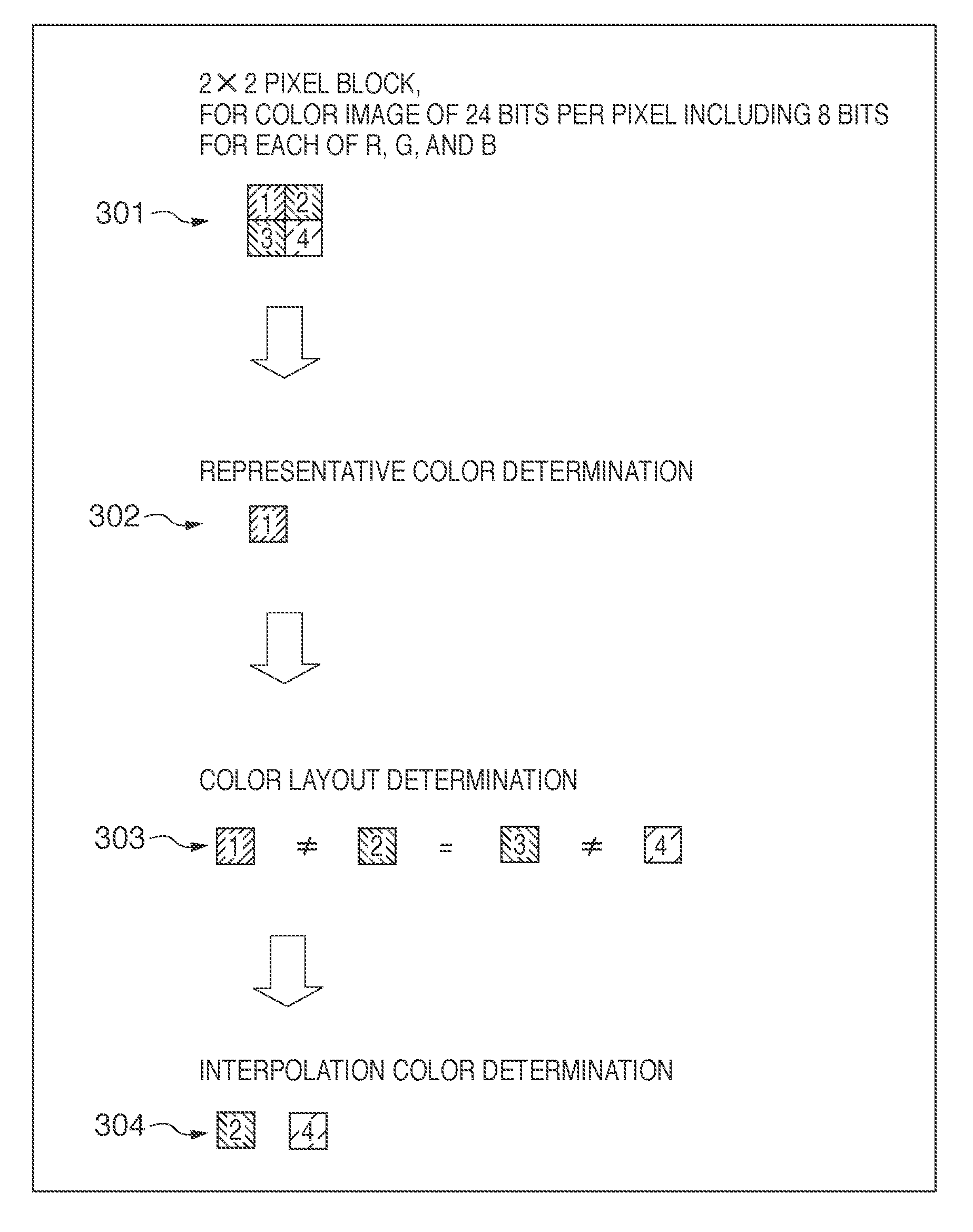
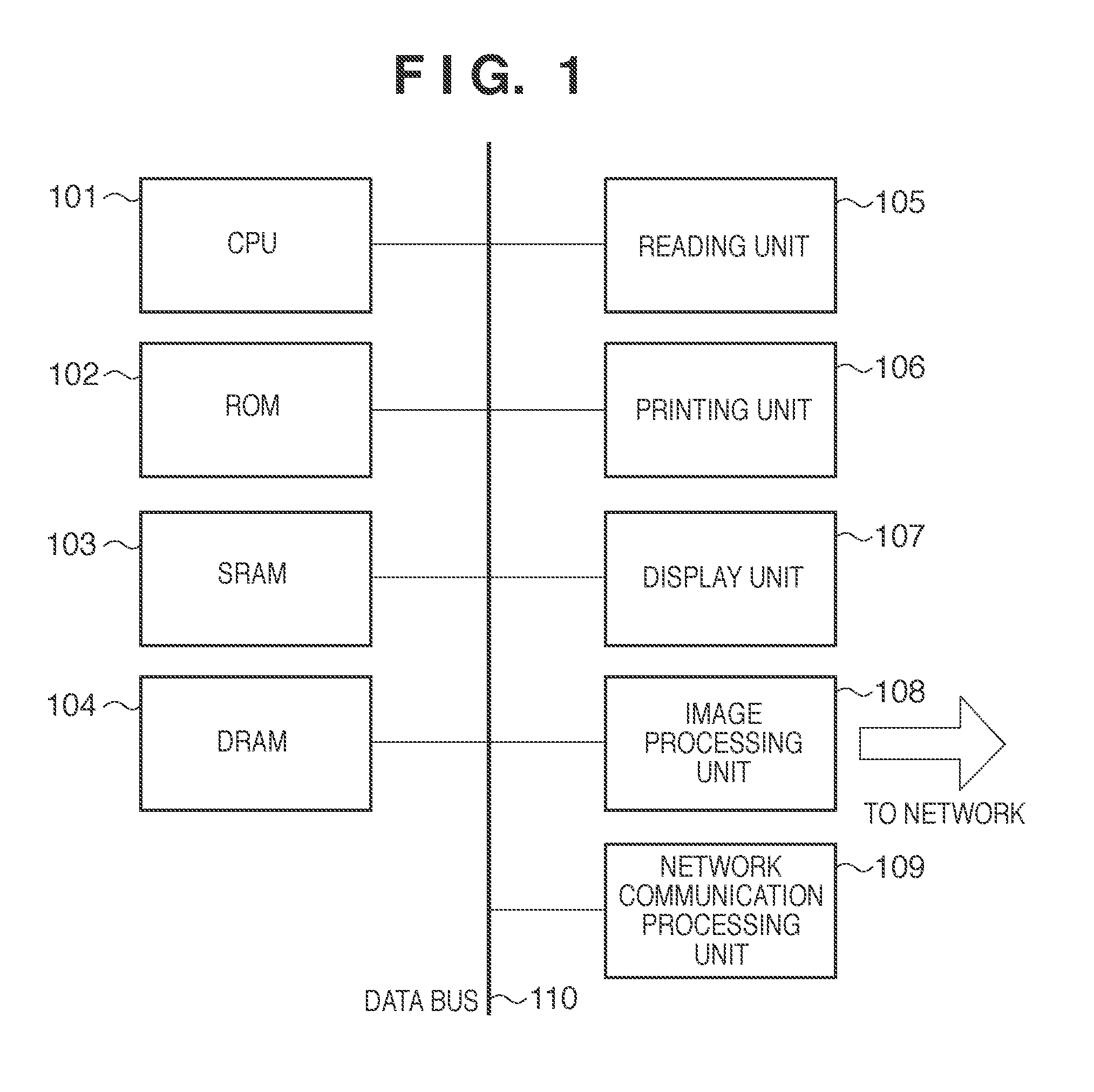
An embodiment of the present invention will now be described with reference to the accompanying drawings. A multi function peripheral will be exemplified as an image processing apparatus. FIG. 1 shows an example of the multi function peripheral. A CPU 101 serves as a system control unit and controls the entire apparatus. A ROM 102 is used to store the control programs of the CPU 101. An SRAM 103 stores set values registered by the operator, management data of the apparatus, and various kinds of work buffers. A DRAM 104 is used to store program control variables, and the like. A reading unit 105 is a device which reads image data and converts it into binary data. Original reading for transmission is performed using the reading unit 105. A printing unit 106 outputs the image data on a printing paper sheet. A display unit 107 serves as a user interface unit which displays information in the device. An image processing unit 108 performs encoding / decoding processing of image data to be h...

second embodiment

In the second embodiment of the present invention, image mask processing by a specific color is implemented by a method different from that of the first embodiment. A description of the same portions as in the first embodiment will not be repeated. FIG. 10 is a view for explaining specific color filling processing according to the second embodiment. The normal decoding procedure indicated by 1001 is the same as in FIG. 7 of the first embodiment, and a description thereof will not be repeated. As is apparent from this decoding method, when filling the 2×2 image block with, for example, white, the representative color is filled with a pixel value representing white. Then, the color layout data is filled with data representing that the image block includes one color. As is apparent, the image is converted into a white image at the time of decoding, as indicated by 1002. The second method of the present invention makes it possible to fill an image with a specific color in a smaller numb...

third embodiment

As the third embodiment of the present invention, a more efficient method that combines the methods of the first and second embodiments will be proposed. In this method, a method with a smaller data filling processing amount is selected by selectively executing the method of the first embodiment and that of the second embodiment. FIG. 13 illustrates a processing procedure according to this embodiment which is executed by a CPU 101.

When processing of filling a packet image with a specific color starts, representative color data is first filled with a pixel value representing the specific color (S1301). Next, the interpolation pixel data amount is compared with the color layout data amount (S1302). If the interpolation pixel data amount is smaller than the color layout data amount, the method of the first embodiment is used to fill the interpolation pixel data with the pixel value representing the specific color (S1303). Conversely, if the color layout data amount is smaller than the ...


PUM


Abstract

An image processing apparatus for performing filling processing for input image data, comprises: a holding unit which holds, for a block formed from a predetermined number of pixels included in the image data, a representative color of the block generated by compression, a color layout of pixels included in the block, and an interpolation color which is a color other than the representative color included in the block; and a fill unit which performs filling processing of the compressed image data using the representative color, the color layout, and the interpolation color, when filling the block of the compressed image data with a specific color, the fill unit replacing the representative color corresponding to a position based on a type of the filling processing with the specific color and replacing the interpolation color with the same specific color as that of the representative color.

Description

BACKGROUND OF THE INVENTION1. Field of the InventionThe present invention relates to a technique of receiving digital image data from outside of a device, storing, processing, and then outputting it.2. Description of the Related ArtAmong image processing apparatuses represented by copying machines and multi function peripherals, image processing apparatuses which have reading and printing units with higher resolution so as to process a high-resolution image are recently becoming popular in order to create a high-quality image. For this reason, the amount of image data to be processed by the device main body is remarkably increasing. Although the device main body needs to store such enormous image data, it is difficult to hold a lot of large image data because of the limited capacity of the main memory. Even when high-speed processing is necessary, the data bus of the main circuit is burdened with the enormous data amount, and therefore, data is transferred slowly, resulting in diffi...

Claims


Application Information

Patent Timeline
Patent Type & Authority Applications(United States)
IPC IPC(8): H04N1/60H04N1/41H04N19/00
CPCG06T9/00H04N1/38H04N19/94H04N19/176H04N1/64
Inventor IKUNO, TAKAO
Owner CANON KK
Learn More