Vibrator driving method, vibrating apparatus, driving apparatus having vibrating apparatus, foreign substance removing apparatus having vibrating apparatus, and optical apparatus having vibrating apparatus

a technology of vibrating apparatus and driving method, which is applied in the direction of motor/generator/converter stopper, dynamo-electric converter control, instruments, etc., can solve the problems of degrading image quality, image arises, and foreign substance adhesion to the optical system during the operation of the apparatus, so as to effectively move an object

Inactive Publication Date: 2011-09-22
CANON KK
View PDF12 Cites 30 Cited by
  • Summary
  • Abstract
  • Description
  • Claims
  • Application Information

AI Technical Summary

Benefits of technology

[0040]According to the present invention, it is possible to achieve the vibrator driving method which enables to effectively move an object including a foreign substance in a predetermined direction by vibration, the vibrating apparatus which uses the vibrator driving method, and the driving apparatus, the foreign substance removing apparatus and the optical apparatus each of which has the vibrating apparatus.

Problems solved by technology

In recent years, with improvement of resolution of an optical sensor in an image pickup apparatus, an adverse influence of a foreign substance adhering to an optical system during operation of the apparatus, on a picked-up image, has come to be considered increasingly serious.
In particular, since the resolution of an image pickup element used in a video camera or a still camera has been remarkably improved, a defect in image arises if the foreign substance adheres to an optical component disposed in the vicinity of the image pickup element.
Thus, a problem of degrading image quality is caused.
However, a foreign substance which adheres to the light ray incident unit during an operation of the apparatus cannot be recognized until after an image has been picked up.
Besides, in the case of a copying machine, such an image is output onto a paper medium simultaneously, whereby it takes a great deal of labor to correct the image.
However, such problems as described below arise in the above-described vibrating apparatus.
Further, in some places, the foreign substances cannot be moved because the in-plane moving directions face to each other, or moving force becomes small in regard to adhesion of the foreign substance.
Thus, efficiency of moving the foreign substance lowers.

Method used


Image

  • Vibrator driving method, vibrating apparatus, driving apparatus having vibrating apparatus, foreign substance removing apparatus having vibrating apparatus, and optical apparatus having vibrating apparatus
  • Vibrator driving method, vibrating apparatus, driving apparatus having vibrating apparatus, foreign substance removing apparatus having vibrating apparatus, and optical apparatus having vibrating apparatus
  • Vibrator driving method, vibrating apparatus, driving apparatus having vibrating apparatus, foreign substance removing apparatus having vibrating apparatus, and optical apparatus having vibrating apparatus

Examples


first embodiment

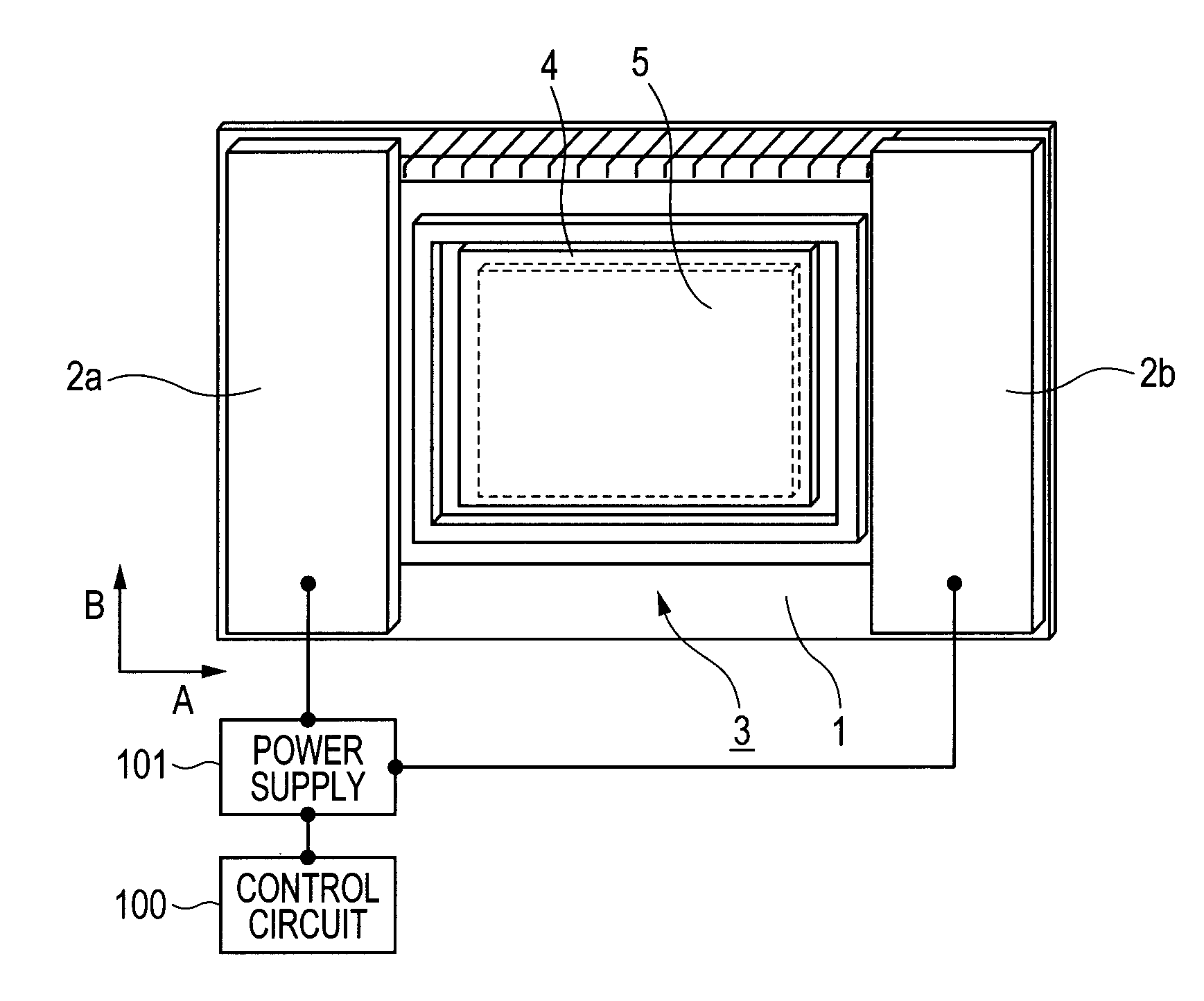
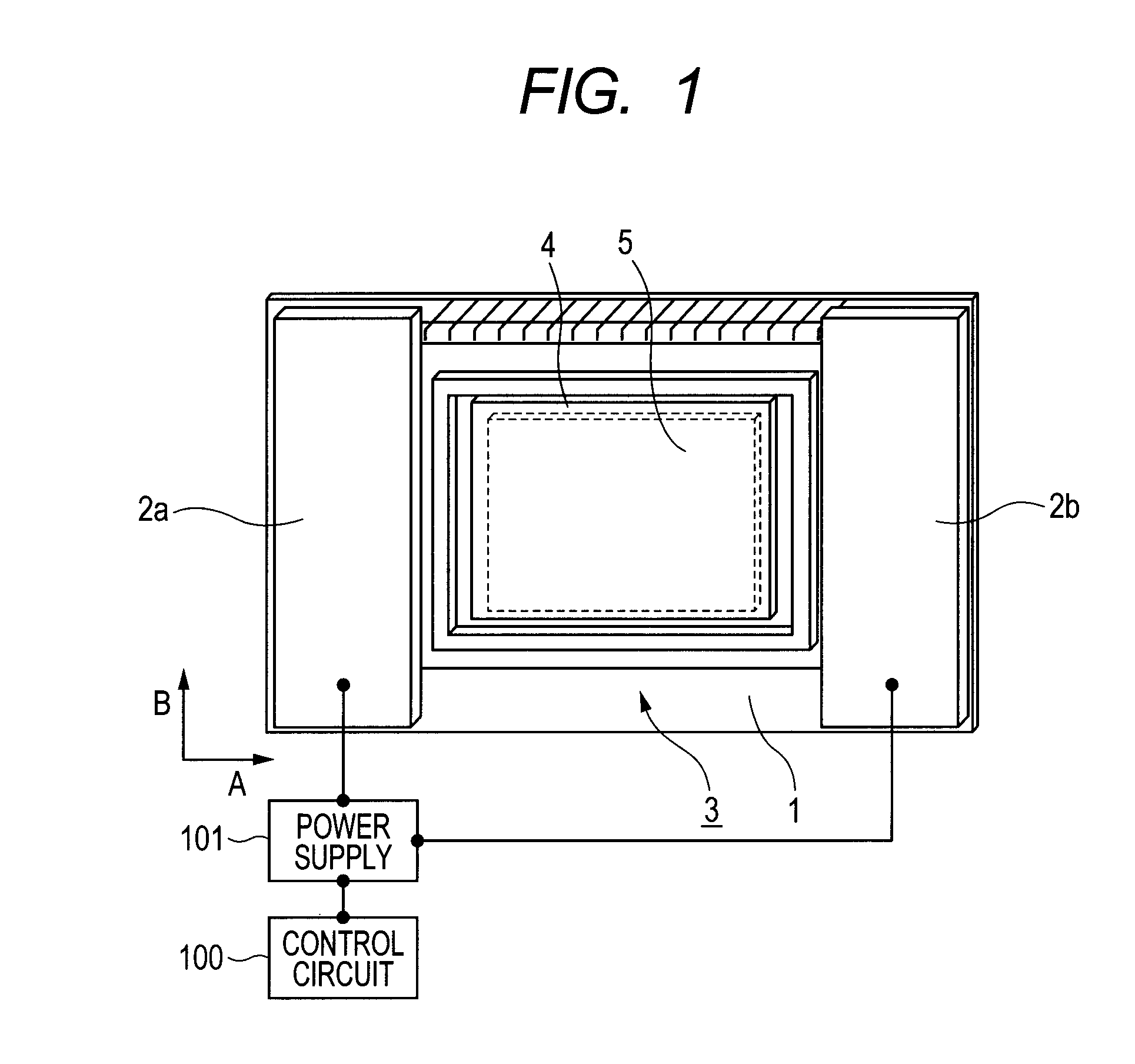
[0059]A constitutional example of a vibrating apparatus provided in a camera, according to the first embodiment of the present invention, will be described with reference to FIG. 1.

[0060]The vibrating apparatus in the present embodiment functions as a foreign substance removing apparatus which removes a foreign substance by moving it.

[0061]In an optical element 1 illustrated in FIG. 1, a piezoelectric element 2 which consists of two electromechanical energy conversion elements (illustrated as piezoelectric elements 2a and 2b) is rigidly glued to the surface on the same side of the side of an image pickup element 4.

[0062]A control circuit 100 sets a frequency, a voltage value and a time phase of an alternating voltage generated by a power supply 101. The power supply 101 is electrically connected to the piezoelectric elements 2a and 2b.

[0063]The optical element 1 and the piezoelectric element 2 together constitute a vibrator 3. The vibrator 3 is attached to the image pickup element ...

second embodiment

[0150]Hereinafter, an example of the vibrator driving method according to the second embodiment of the present invention will be described.

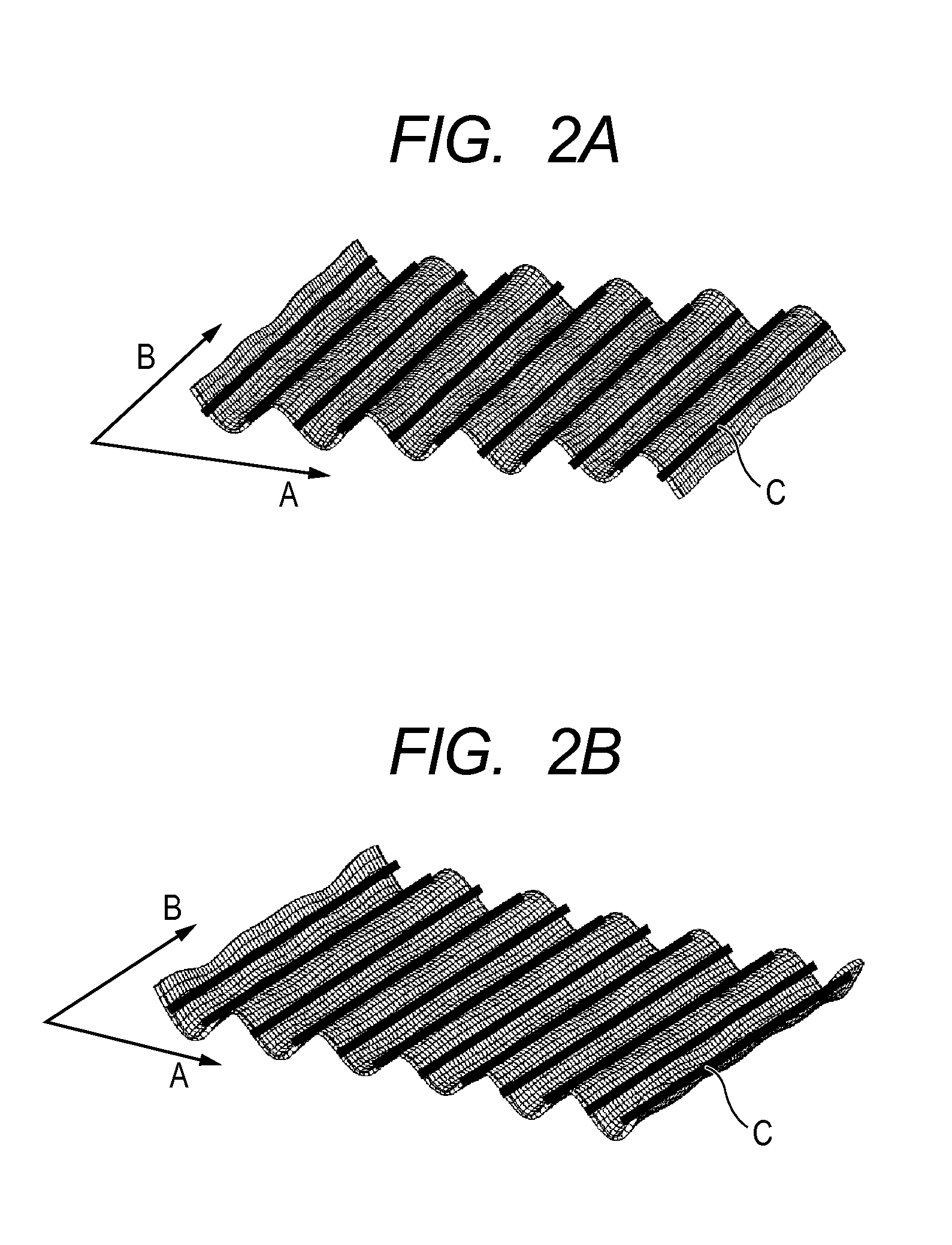
[0151]In the present embodiment, the two vibrations which are synthesized to move the foreign substance are indicated by the vibration modes illustrated in FIGS. 5A-1, 5A-2, 5B-1 and 5B-2.

[0152]One vibration mode is the vibration mode (FIGS. 5A-1 and 5A-2) in which tenth-order out-of-plane bending deformation arises in the right-and-left direction (first direction A) and first-order out-of-plane bending deformation arises in the up-and-down direction (second direction B).

[0153]In the present embodiment, the relevant vibration mode is called a first vibration mode.

[0154]Next vibration mode is the vibration mode (FIGS. 5B-1 and 5B-2) in which eleventh-order out-of-plane bending deformation arises in the right-and-left direction (first direction A) and first-order out-of-plane bending deformation arises in the up-and-down direction (second direction...

third embodiment

[0216]In the first embodiment, the driving method of setting the magnitude of the voltage is described as the method of setting the magnitude of the excitation force for the first vibration mode and the second vibration mode.

[0217]In the present embodiment, the vibrating apparatus in which the divided electrodes 9 of the piezoelectric element 2 are effectively arranged will be described. Incidentally, the present embodiment is different from the first embodiment in that point that the magnitudes of the voltage (sum) and the voltage (different) are set to be the same. Further, the arrangement of the divided electrodes 9 of the piezoelectric element 2 in the present embodiment is different from that in the first embodiment.

[0218]Subsequently, the arrangements of the nodal lines and the respective piezoelectric elements 2 in the tenth-order out-of-plane bending vibration mode (first vibration mode) and the eleventh-order out-of-plane bending vibration mode (second vibration mode) and c...


PUM


Abstract

A driving method causes a vibrator to generate standing waves different in order with a predetermined time phase difference. The vibrator has a first vibration mode that plural nodal lines are arranged in a first direction, a second vibration mode that number of first-direction nodal lines is different from that in the first vibration mode and its natural frequency is higher than that of the first vibration mode, and a third vibration mode that its natural frequency is between those of the first and second vibration modes. The vibrator is driven on condition that excitation force to one of the first and second vibration modes that a difference between its natural frequency and the natural frequency of the third vibration mode is smaller is made larger than that to the other thereof that a difference between its natural frequency and the natural frequency of the third vibration mode is larger.

Description

BACKGROUND OF THE INVENTION[0001]1. Field of the Invention[0002]The present invention relates to a vibrator driving method and a vibrating apparatus. In particular, the present invention relates to a vibrating apparatus which is used in a foreign substance removing apparatus of an optical apparatus such as a camera, a facsimile apparatus, a scanner, a projector, a copying machine, a laser beam printer, an inkjet printer, a lens, binoculars, an image displaying apparatus or the like, and a driving apparatus which drives an object by vibration.[0003]2. Description of the Related Art[0004]In recent years, with improvement of resolution of an optical sensor in an image pickup apparatus, an adverse influence of a foreign substance adhering to an optical system during operation of the apparatus, on a picked-up image, has come to be considered increasingly serious.[0005]In particular, since the resolution of an image pickup element used in a video camera or a still camera has been remarkab...

Claims


Application Information

Patent Timeline
Patent Type & Authority Applications(United States)
IPC IPC(8): B60R1/00H02K33/00F28G7/00
CPCG02B27/0006G03B17/02H04N5/2171H01L41/0913H01L41/042H04N23/811H10N30/802H10N30/2023B08B7/02
Inventor OHASHI, KAISHI
Owner CANON KK
Why Eureka
Try Eureka