Auto-correcting or self-calibrating DTS temperature sensing systems and methods

a temperature sensing system and self-calibration technology, applied in the field of temperature sensing, can solve the problems of poor calibration, simple method, higher performance data acquisition components, etc., and achieve the effect of economic and simple solutions

Inactive Publication Date: 2011-09-22
SUH KWANG +3
View PDF15 Cites 41 Cited by
  • Summary
  • Abstract
  • Description
  • Claims
  • Application Information

AI Technical Summary

Benefits of technology

[0016]The present disclosure provides economic and simple solutions to determining an accurate temperature profile in a distributed temperature optical fiber sensing system, and more particularly for correcting error generated by the ambiguities in a local sensing fiber cable's attenuation profile. In all of these schemes there is a primary light source used for temperature measurement and a correcting light source that is used only intermittently. The key to these schemes is that the primary light source is used exclusively and for the majority of the time to measure temperatures. The correcting light source is only used when needed to correct for errors in the system. The choice...

Problems solved by technology

One problem involved in the operation of DTS systems is proper calibration.
Localized mechanical stress or strain, fiber crimping, chemical attack (eg. hydrogen ingression) all can induce abnormalities, and some of these can change with time.
The time domain method is simpler than frequency domain analysis but it requires a costly pulsed light source and higher performance data acquisition components but has lower signal to noise characteristics.
With such approaches either the availability of desired light sources or the issue of cost have been obstacles to a practical implementation.
These may double the length of sensing fiber and the sensing time, require an extra monitoring channel, and are not universally applicable in...

Method used


Image

  • Auto-correcting or self-calibrating DTS temperature sensing systems and methods
  • Auto-correcting or self-calibrating DTS temperature sensing systems and methods
  • Auto-correcting or self-calibrating DTS temperature sensing systems and methods

Examples


experimental verification

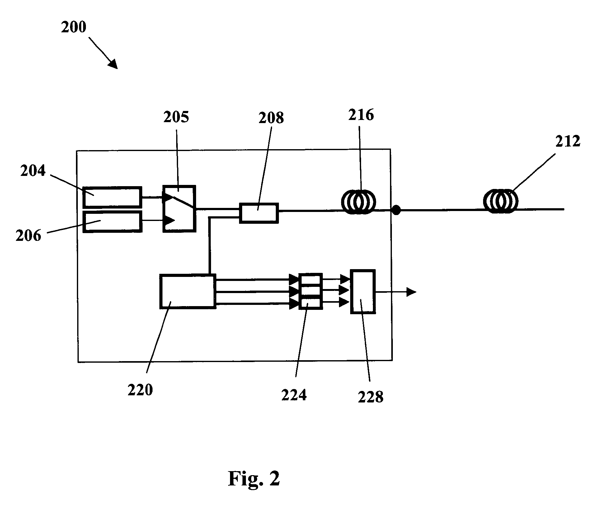
[0060]In an experimental set-up similar to FIG. 2 two laser sources 975 nm (primary) and 940 nm (secondary) were operated in pulse mode and selected alternatively using an optical switch, and the scattered signals collected in sequence by Si APD (Avalanche Photo-Diodes). The anti-Stokes signal is collected with 975 nm laser connection selected, while the Stokes signal is collected with the 940 nm laser selected. A back-scattered spectrum of the single source system is shown in FIG. 4 and the proposed dual-source system back-scattered Raman intensities are plotted in FIG. 5. Two solid lines located at 940 nm and 975 nm indicate the Rayleigh bands of the secondary and the primary light sources. And two dotted lines containing the solid lines indicate the anti-Stokes and Stokes bands of the primary and secondary light sources respectively.

[0061]Four different multimode fibers were used for test probes—three fibers in normal condition from different manufacturers, and one fiber that is ...


PUM


Abstract

An automatic auto-correcting method is presented to improve the accuracy of fiber optic distributed temperature measurements derived from Raman back scatterings utilizing two light sources with different wavelengths, by appropriate choice of the wavelengths of the two sources, the use of single pulse modulating circuit for the two light sources, and use of one of the light sources as a primary measurement system and the second light source as an occasional correcting source.

Description

FIELD AND BACKGROUND[0001]1. Field of the Invention[0002]The present invention relates generally to temperature sensing, and more particularly, to dual source self-calibration or auto-correction systems and methods for distributed temperature sensing.[0003]2. Background of the Invention[0004]Fiber optic Distributed Temperature Sensing (DTS) systems were developed in the 1980s to replace thermocouple and thermistor based temperature measurement systems. DTS technology is based on Optical Time-Domain Reflectometry (OTDR) and utilizes techniques originally derived from telecommunications cable testing. Today DTS provides a cost-effective way of obtaining hundreds, or even thousands, of highly accurate, high-resolution temperature measurements, DTS systems today find widespread acceptance in industries such as oil and gas, electrical power, and process control.[0005]The underlying principle involved in DTS-based measurements is the detection of spontaneous Raman back-scattering. A DTS s...

Claims


Application Information

Patent Timeline
IPC IPC(8): G01K15/00G06F19/00
CPCG01K11/32G01K2011/324G01K15/005G01K15/00G01K11/324
Inventor SUH, KWANGKALAR, KENTLEE, CHUNGSANDERS, MICHAEL
Owner SUH KWANG
Why Eureka
Try Eureka