
Thermally assisted magnetic recording medium and magnetic recording storage

Active Publication Date: 2011-09-29
SHOWA DENKO KK
View PDF3 Cites 20 Cited by
  • Summary
  • Abstract
  • Description
  • Claims
  • Application Information

AI Technical Summary

Benefits of technology

[0010]Another object of the present invention is to provide a magnetic recording storage which is provided with a thermally assisted magnetic recording medium having the above-mentioned benefits, and exhibits a high SN ratio and good overwriting characteristics.

Problems solved by technology

However, when an exchange coupling between magnetic grains is strong, adjacent magnetic grains are bonded together to form a large magnetic cluster resulting in enhancement of the media noise.
However, when a limited amount of a grain boundary segregation material is added, the width of grain boundaries tend to decrease with a decrease in grain size.

Method used


Image

  • Thermally assisted magnetic recording medium and magnetic recording storage
  • Thermally assisted magnetic recording medium and magnetic recording storage
  • Thermally assisted magnetic recording medium and magnetic recording storage

Examples


examples

[0059]The thermally assisted magnetic recording medium and the magnetic recording storage according to the present invention will now be specifically described by the following examples.

examples 1-1 to 1-8

, and Comparative Example 1

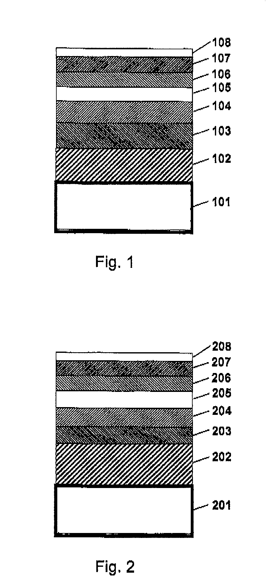
[0060]Thermally assisted magnetic recording media having a multilayer structure as illustrated in FIG. 1 were manufactured as follows.

[0061]A Co-50 atomic % Ti alloy underlayer (102) having a thickness of 30 nm and an Fe-20 atomic % Al-5 atomic % Si alloy soft magnetic underlayer (103) having a thickness of 25 nm were formed in turn on a glass substrate (101). Then the two underlayers-formed substrate was heated to 250° C., and a Cr-20 atomic % V alloy underlayer (104) having a thickness of 10 nm was formed thereon. Then a MgO-containing underlayer (105) having a thickness of 5 nmm was formed, and then the substrate was heated to 420° C. Thereafter, (Fe-55 atomic % Pt) −14 mol % TiO2 magnetic layer (106) having a thickness of 6 nm, Co-10 atomic % Ta-5 atomic % B cap layer (107) having a thickness of 2 nm and then a diamond-like carbon (DLC) protective overcoat (108) having a thickness of 3 nm were formed in this order.

[0062]As the MgO-containing underlayer...

examples 2-1 to 2-10

, and Comparative Example 2

[0069]Thermally assisted magnetic recording media having a multilayer structure as illustrated in FIG. 2 were manufactured as follows.

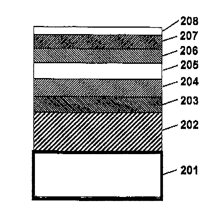
[0070]A Ag heat sink layer (202) having a thickness of 100 nm, an Fe-10 atomic % Ta-12 atomic % C alloy soft magnetic underlayer (203) having a thickness of 100 nm and a Ta underlayer (204) having a thickness of 10 nm were formed in this order on a glass substrate (201). Then a MgO-containing underlayer (205) having a thickness of 3 nmm was formed, and then the substrate was heated to 420° C. Thereafter, (Fe-50 atomic % Pt) -45 atomic % C magnetic layer (206) having a thickness of 10 nm, Co-10 atomic % Ta-5 atomic % Zr cap layer (207) having a thickness of 2 nm and then a DLC protective overcoat (208) having a thickness of 3 nm were formed in this order.

[0071]As the MgO-containing underlayer (205) , each of the following compositions: MgO-6 atomic % A1-3 atomic % Si, MgO-10 atomic % Si-5 atomic % Cr, MgO-5 atomic % Si-5 atom...


PUM


Abstract

Disclosed is a thermally assisted magnetic recording medium comprising a substrate, a plurality of underlayers formed on the substrate, and a magnetic layer which is formed on the underlayers and predominantly comprised of an alloy having an L10 structure, characterized in that at least one of said underlayers is predominantly comprised of MgO and comprises at least one kind of an element having a free energy for oxidation of, per mol of oxygen, not higher than −120 kcal / mol·O2 at 1000° C. The element having the free energy for oxidation is preferably selected from Al, Si, Ti, V, Cr, Mn, Zr and B . The thermally assisted magnetic recording medium has a magnetic layer comprised of magnetic crystal grains with uniform diameters, and exhibiting a sufficiently weak exchange coupling between magnetic grains.

Description

TECHNICAL FIELD[0001]This invention is concerned with a thermally assisted magnetic recording medium, and a magnetic recording storage provided with the thermally assisted magnetic recording medium.BACKGROUND OF THE INVENTION[0002]In thermally assisted magnetic recording wherein a magnetic recording medium is irradiated with an evanescent light whereby the surface of the medium is locally heated and the coercive force of the medium is decreased, and writing is effected. This thermally assisted magnetic recording attracts attention as a magnetic recording system of the next generation which is capable of realizing a high plane recording density of approximately 1 T bit / inch2 or larger. In the case when the thermally assisted magnetic recording system is adopted, even when a recording medium having a coercive force of several tens kOe (note, 10 Oe equals to approximately 79 A / m) at room temperature is used, writing can easily be effected with a magnetic head having the currently avail...

Claims


Application Information

Patent Timeline
IPC IPC(8): G11B13/04G11B5/73
CPCG11B5/7325G11B5/65G11B5/7366G11B5/7369G11B5/737G11B5/658
Inventor KANBE, TETSUYAHASHIMOTO, ATSUSHIFUKUSHIMA, TAKAYUKI
Owner SHOWA DENKO KK
Learn More