Vacuum processing apparatus and vacuum transfer apparatus

a vacuum transfer and processing apparatus technology, applied in the field of vacuum transfer apparatus and vacuum transfer apparatus, can solve the problems of transfer robots not responding, vacuum transfer apparatus side failing to follow an entire process capability, and the burden of vacuum transfer apparatus increasing, so as to achieve simple and efficient mechanism and operation, the effect of remarkably improving the transfer capability

Active Publication Date: 2011-09-29
TOKYO ELECTRON LTD
View PDF9 Cites 16 Cited by
  • Summary
  • Abstract
  • Description
  • Claims
  • Application Information

AI Technical Summary

Benefits of technology

[0033]According to a vacuum processing apparatus or a vacuum transfer apparatus of the present invention, transfer capability is remarkably improved by using a vacuum transfer robot having a simple and efficient mechanism and operation without having to extend a longitudinal space of a platform downward in a cluster tool, according to the above structures and operations.

Problems solved by technology

As such, when the number of installed process chambers increases, the burden of the vacuum transfer apparatus increases, and thus a transfer capability of a vacuum transfer apparatus side failing to follow an entire process capability of a processing apparatus side has become a problem.
Although, such a circulating pick and place method effectively functions when a process time of each process module is sufficiently long compared to a transfer time, since a transfer operation of the transfer robot has a time to spare, when the process time is short, it becomes difficult for the transfer robot to respond, and thus transfer efficiency or throughput decreases.
Meanwhile, if a post-process (for example, purging, cleaning, or the like), which is performed in the process module immediately after the target object that has been processed is transferred out (picked), takes a long time, the transfer robot has to wait in front of the process module until the post-process is completed so as to perform a place operation with respect to the possessed unprocessed target object, and thus throughput of the overall system remarkably deteriorates due to this long standby time.
Also, due to the trend of the increasing number of installed process modules (process chambers) as described above, performing all substrate transfer operations in the platform by using one vacuum transfer robot has reached the limit.

Method used


Image

  • Vacuum processing apparatus and vacuum transfer apparatus
  • Vacuum processing apparatus and vacuum transfer apparatus
  • Vacuum processing apparatus and vacuum transfer apparatus

Examples


Embodiment Construction

[0052]Hereinafter, embodiments of the present invention will be described in detail with reference to the attached drawings.

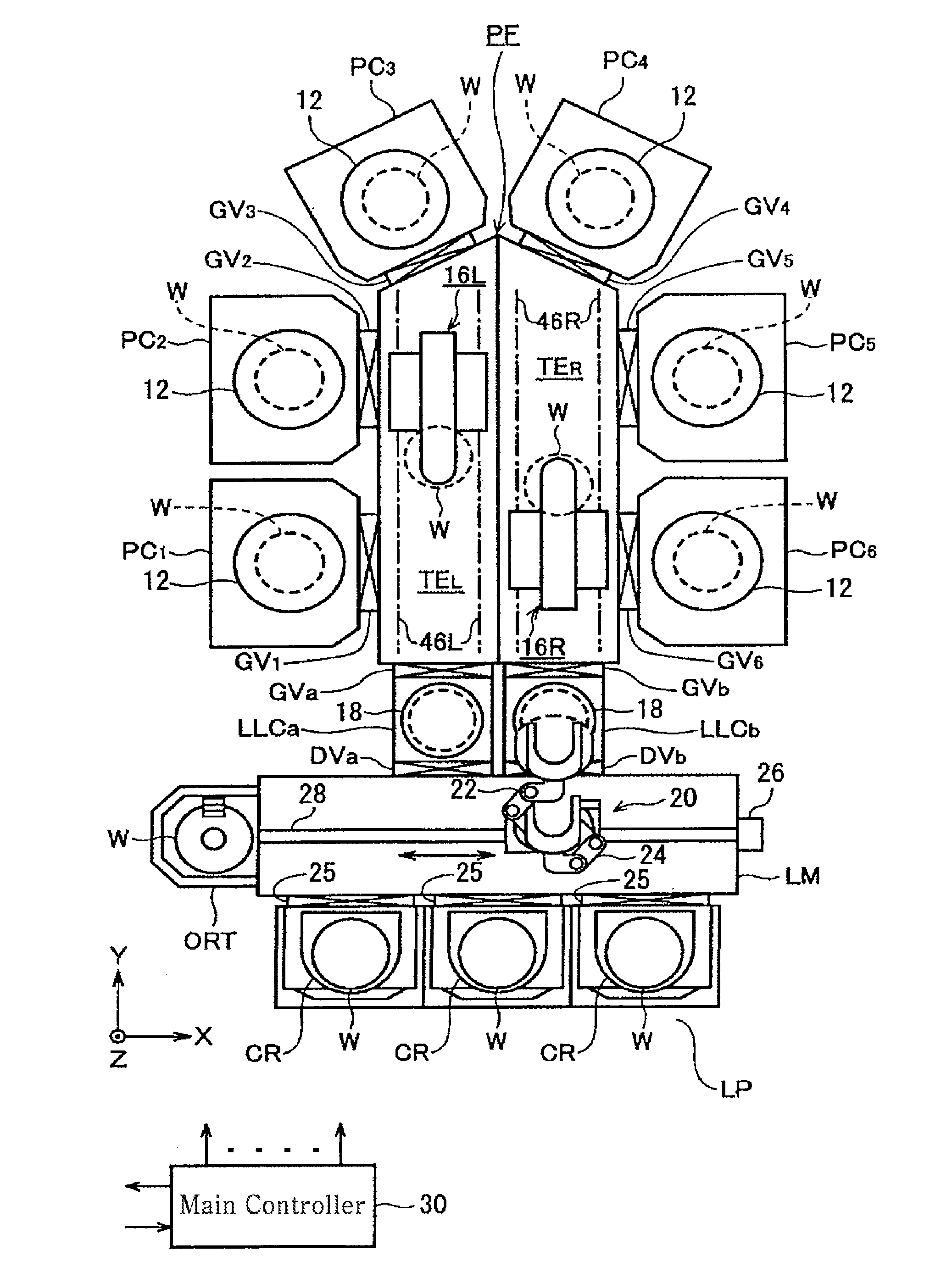
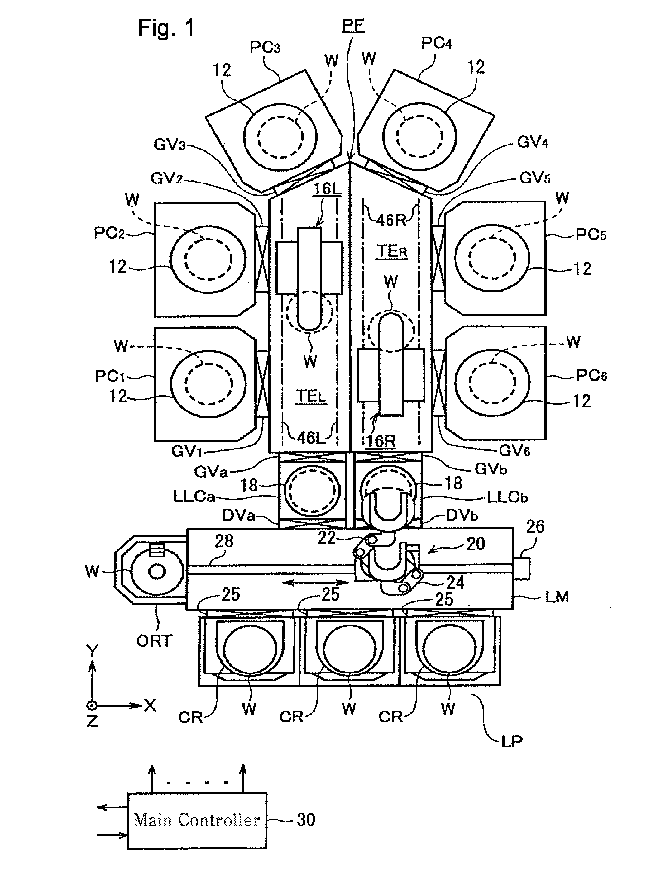
[0053]FIG. 1 shows the whole configuration of a vacuum processing apparatus of a cluster tool type, according to an embodiment of the present invention. The vacuum processing apparatus is installed in a clean room, and includes six vacuum process chambers PC1, PC2, PC3, PC4, PC5, and PC6 and two load lock chambers LLCa and LLCb adjacent to and around a vacuum platform (vacuum transfer chamber) PF having a pentagon shape of which a pair of sides extending in an inner depth direction (Y direction in FIG. 1) in the apparatus are about twice longer than the other sides arranged in a cluster shape.

[0054]In detail, the platform is connected to, in a clockwise order in FIG. 1, the first and second process chambers PC1 and PC2 respectively through gate valves GV1 and GV2 on a long left side, the third and fourth process chambers PC3 and PC4 respectively through gate va...


PUM


Abstract

Transfer capability is improved without having to extend a longitudinal space of a platform of a cluster tool downward. In a platform PF, a first transfer robot 16L includes a transfer main body 48L that is slidable on a left guide rail 46L, a transfer pedestal 50L that is slidable in an offset direction (X direction), and a slider type transfer arm 52L that is rotatable within a horizontal surface while being movable straight in a direction parallel to a radius of a rotation circle and supports one piece of a semiconductor wafer W. A second transfer robot 16R has the same configuration and operations as the first transfer robot 16L except that an operation or moving direction of each component of the second transfer robot 16R is vertically symmetrical to that of the first transfer robot 16L.

Description

TECHNICAL FIELD[0001]The present invention relates to a vacuum processing apparatus and a vacuum transfer apparatus of a cluster tool type.BACKGROUND ART[0002]A cluster tool type is well-known as a type of a vacuum processing apparatus having a vacuum transfer chamber. In the cluster tool type apparatus, a plurality of process chambers, where predetermined processes are performed at a depressurized state, are disposed around a vacuum platform so as to promote consistency, connectivity, or compositeness of processes. The cluster tool type is also referred to as a multi-chamber type, and is typically employed by a semiconductor manufacturing apparatus (for example, refer to Patent Document 1).[0003]Generally, in a cluster tool, one target object is sequentially transferred to the plurality of process chambers so that the same type or different types of vacuum process is continuously performed on the target object. In the semiconductor device manufacture, a CVD (chemical vapor depositi...

Claims


Application Information

Patent Timeline
Patent Type & Authority Applications(United States)
IPC IPC(8): B25J9/10
CPCH01L21/67742H01L21/67196B25J5/02B25J11/0095H01L21/6719H01L21/67201H01L21/6838H01L21/68707
Inventor HIROKI, TSUTOMU
Owner TOKYO ELECTRON LTD
Why Eureka
Try Eureka