Multilayer devices on flexible supports

a multi-layer device and flexible support technology, applied in the field of flexible support, can solve the problems of increasing manufacturing cost, affecting the flexibility of the substrate, and affecting the stability of the device, so as to achieve the flexibility and transparency of the substrate, and the stress in the thin layer of an element in accordance with the invention. significant

Inactive Publication Date: 2011-10-06
EASTMAN KODAK CO
View PDF3 Cites 23 Cited by
  • Summary
  • Abstract
  • Description
  • Claims
  • Application Information

AI Technical Summary

Benefits of technology

[0019]The stress in the thin layers of an element in accordance with the invention is significantly reduced, whilst maintaining an overall thickness of support, and the flexibility and transparency of the substrate. It also allows incorporation of a glass component in the support as an effective barrier to oxygen and moisture.

Problems solved by technology

Thin multilayer devices, exemplified by a traditional OLED device, and in particular the electrodes and organic layers located therein, are susceptible to degradation resulting from interaction with oxygen and moisture leaking into the device from the ambient environment.
Rigidity excludes roll-to-roll device fabrication processes thus adding cost to manufacture, and the disproportionate weight also adds cost to distribution and installation.
Polymeric substrates, as alternative lightweight and flexible supports, are particularly susceptible to permeation of moisture and oxygen.
This preserves the lightweight, flexible and transparent characteristics of the support, but has the disadvantage that the protection achieved does not reach that of a single thicker glass layer in the thickness range of 10 μm or more.
In many electronic devices, inorganic materials typically used as conductors, such as transparent conductive oxides, or semiconductors, such as amorphous silicon and silicon nitride, are brittle and crack easily when substrates are deformed.
In general, inorganic materials are more brittle and crack more easily than organic materials, at least in the context of materials commonly used to fabricate organic electronic devices.
However, the ITO films are limited in their applications due to their brittleness and low tolerance to stress.
Even minute fractures in an ITO film can cause a rapid loss of conductivity and a disadvantageous increase in its sheet resistance.
However, deposition on an initially thick substrate, however, would preclude a roll-to-roll deposition process.
However, after separation from the mother substrate, the stress in a brittle thin layer of the device is not necessarily relieved.
Fractures may be protected against, but the inherent stress within the brittle layer is not relieved.
However, strain protection in the thin multilayer device will only be afforded to the finished OLED device.
In summary, there are situations where it is not practical to reduce the overall thickness of the support, or rely solely on fracture protection, in an effort to preserve the integrity of particularly the more brittle, but crucial, thin layers, such as ITO in a multilayer device.

Method used


Image

  • Multilayer devices on flexible supports
  • Multilayer devices on flexible supports
  • Multilayer devices on flexible supports

Examples


example 1

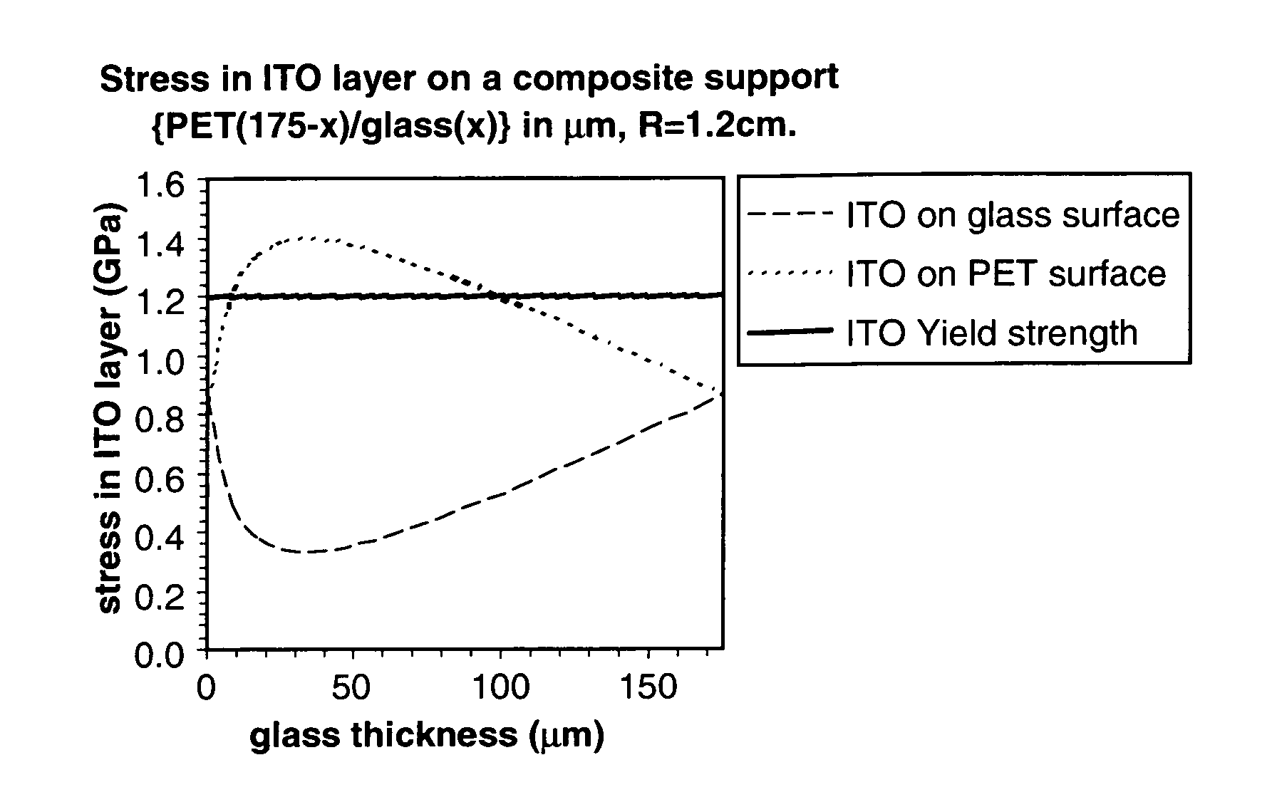
[0040]A composite support comprising two layers: PET and flexible glass, having a constant total thickness of 175 μm is subjected to applied stress with a tight bending radius of 1.2 cm. The stress in a thin ITO layer deposited on one, or the other, of the two surfaces of the support, can be simulated. The result is shown in FIG. 1, in comparison to the yield strength of ITO. In the case of ITO deposited on the PET surface, all proportions cause an increase in stress in the ITO over the 100% glass, or 100% PET, compositions. In the region around the maximum, the yield strength of ITO is exceeded. On the other hand, if ITO is deposited on the glass surface, there is a clear minimum of stress for the same proportions. Clearly, it is preferable to deposit ITO on the glass surface to protect the ITO integrity. These results are summarised in Table 1.

TABLE 1Calculated stress in a thin ITO layer on different PET / glass support compositionsfor a radius of curvature of 1.2 cm. The moduli of ...

example 2

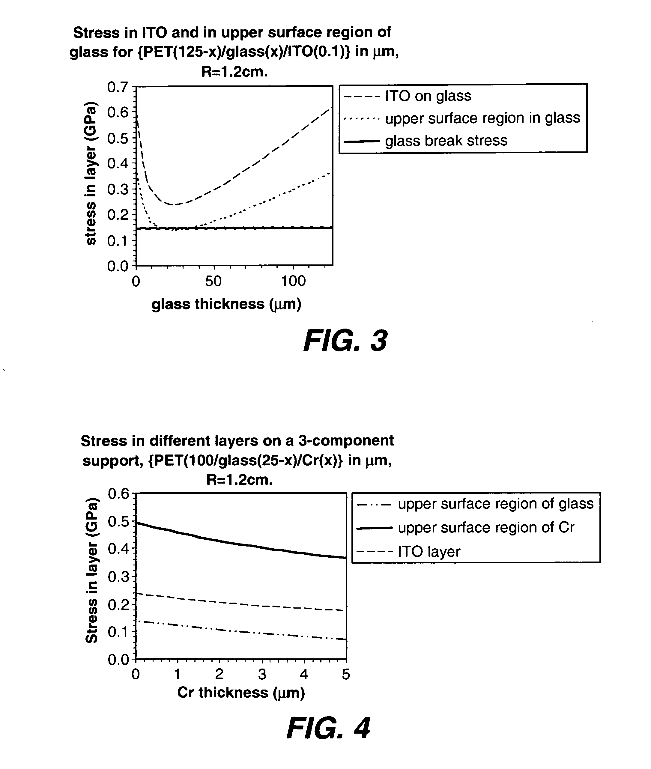
[0043]In this series, a composite support comprising 3 layers: {PET / flexible glass / chromium} of total thickness 125 μm, the layer ordering shown, and subjected to a bend radius of 1.2 cm. Chromium has a Young's modulus value of 248 GPa, and a breaking stress of 0.41 GPa. FIG. 4 shows the effect of an additional chromium layer to the support on the ITO stress, and in the regions of highest stress in the glass and chromium layers of the substrate. The starting position (Cr=0 μm) approximates closely to the optimum position in shown in FIG. 3. As the proportion of the chromium is increased at the expense of the flexible glass layer, the stresses in the three regions: the upper surface region of the glass nearest glass / Cr interface, the upper surface region of the Cr nearest the Cr / thin multilayer interface, and the thin ITO layer, are all reduced. However, the introduction of chromium requires that the breaking stress of this material (0.41 GPa) is not exceeded—in this example a layer ...


PUM

PropertyMeasurementUnit
thicknessaaaaaaaaaa
thicknessesaaaaaaaaaa
thicknessaaaaaaaaaa

Abstract

A flexible element has a flexible support comprising two or more layers with different modulus of elasticities in bound contact with each other, and at least one thin film wherein the total thickness of the thin film(s) is less than the total thickness of the flexible support at any point of contact between the support and the thin film(s); and at least one thin film is deposited on the outer surface of the layer of the flexible support having the higher elastic modulus.

Description

FIELD OF THE INVENTION[0001]This invention relates to a flexible support, consisting of a flexible plastic on glass composition, which lessens the mechanical stress in all thin layers on the support, particularly the brittle and sensitive components of a thin multilayer, preferably an OLED device, and particularly during deposition of successive thin layers in a roll-to-roll process.BACKGROUND OF THE INVENTION[0002]Thin multilayer devices, exemplified by a traditional OLED device, and in particular the electrodes and organic layers located therein, are susceptible to degradation resulting from interaction with oxygen and moisture leaking into the device from the ambient environment. The life of an OLED display, for example, can be increased significantly if the electrodes and organic layers within the OLED display are protected from moisture and oxygen, which may destroy them if they reach the thin active layers. For instance, supports, encapsulants and hermetic seals should provide...

Claims


Application Information

Patent Timeline
Patent Type & Authority Applications(United States)
IPC IPC(8): H01L33/62H01L33/02B32B7/02
CPCB32B17/10009B32B17/10027B32B17/10174B32B27/36Y10T428/2495H01L51/50H01L51/5237Y02E10/549H01L51/0097B32B2250/03B32B2255/205B32B2307/412B32B2307/54B32B2307/7244B32B2307/7265B32B2457/206H10K77/111H10K50/00H10K50/844
Inventor WINSCOM, CHRISTOPHER JOHN
Owner EASTMAN KODAK CO
Why Eureka
Try Eureka