Fuel cell system

Inactive Publication Date: 2011-10-06
SAMSUNG SDI CO LTD
View PDF4 Cites 4 Cited by
  • Summary
  • Abstract
  • Description
  • Claims
  • Application Information

AI Technical Summary

Benefits of technology

[0011]Embodiments of the present invention provide a fuel cell system that has a simplified configuration by being able to supply an oxidizing agent containing moisture to a

Problems solved by technology

However, in this case, water should be continuously supplied to the humidifying device and a heater and various sensors ar

Method used


Image

  • Fuel cell system
  • Fuel cell system
  • Fuel cell system

Examples


Embodiment Construction

[0031]The present invention will be described more fully hereinafter with reference to the accompanying drawings, in which exemplary embodiments of the invention are shown. As those skilled in the art would realize, the described embodiments may be modified in various different ways, all without departing from the spirit or scope of the present invention.

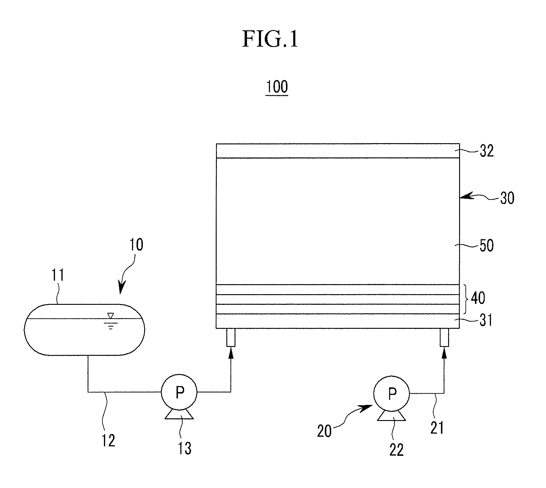
[0032]FIG. 1 shows a schematic diagram of a fuel cell system according to a first exemplary embodiment of the present invention.

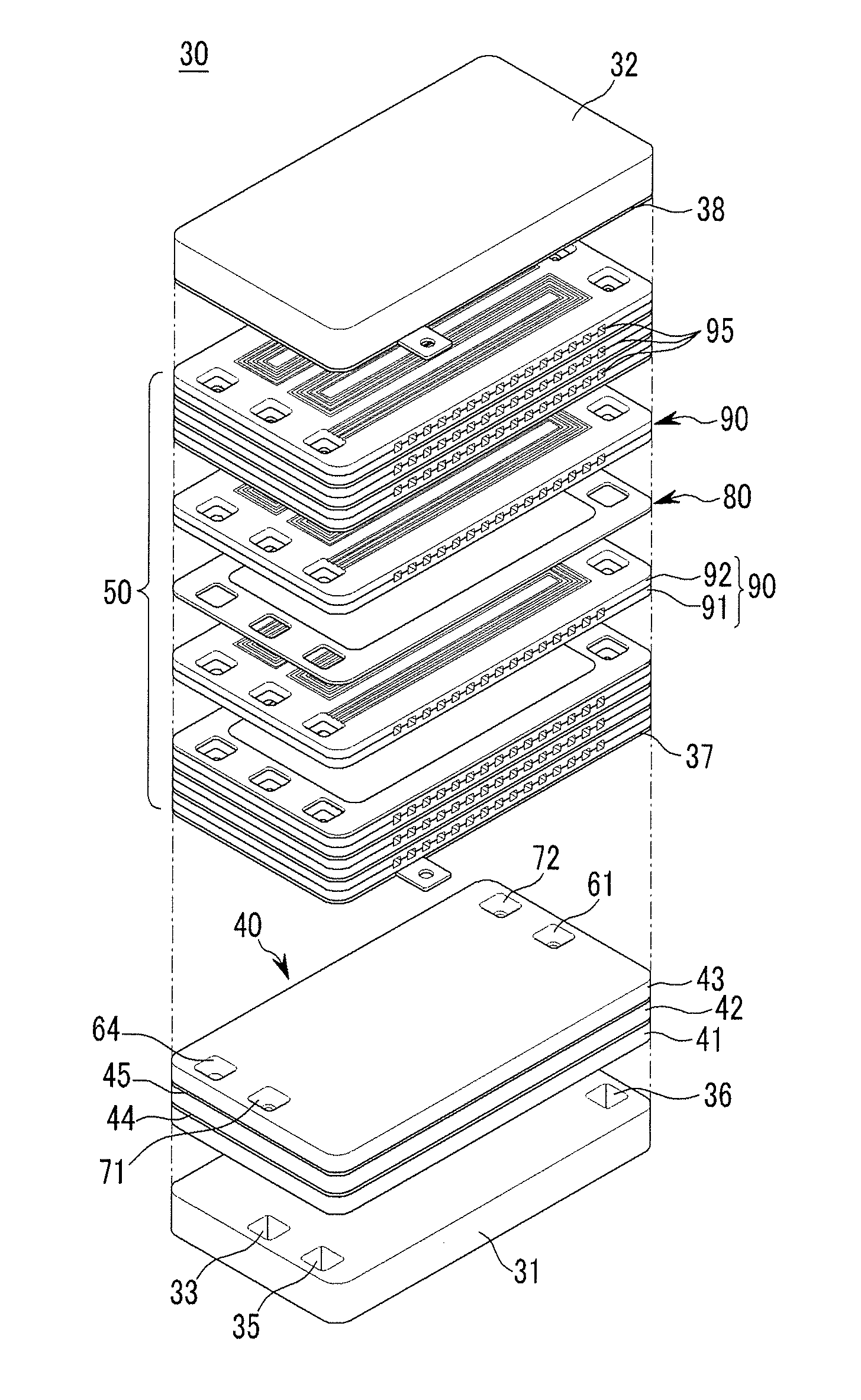
[0033]Referring to FIG. 1, a fuel cell system 100 according to the first exemplary embodiment includes a fuel cell stack 30, a fuel supply 10 supplying a fuel to the fuel cell stack 30, and an oxidizing agent supply 20 supplying an oxidizing agent to the fuel cell stack 30.

[0034]The fuel is a hydrocarbon-based fuel existing in a liquid or gas state such as methanol, ethanol, liquefied natural gas, gasoline, and butane gas, and the oxidizing agent is external air or oxygen gas. The fuel cell system 100 may b...


PUM


Abstract

The fuel cell system includes a fuel cell stack, a fuel supply supplying a fuel to the fuel cell stack, and an oxidizing agent supply supplying an oxidizing agent to the fuel cell stack. The fuel cell stack includes a first end plate, a moisture exchanger, an electrical generator, and a second end plate. The moisture exchanger includes a first area where a dried supply oxidizing agent flows, a second area where a humid emission fuel flows, and a third area where a humid emission oxidizing agent flows, and the first area exchanges moisture with the second and third areas using a moisture exchange layer.

Description

CROSS-REFERENCE TO RELATED APPLICATIONS[0001]This application claims the benefit of U.S. Provisional Application Nos. 61 / 321,398, filed on Apr. 6, 2010, and 61 / 323,280, filed on Apr. 12, 2010, in the United States Patent and Trademark Office, the disclosures of which are incorporated herein in their entirety by reference.BACKGROUND[0002]1. Field[0003]The present invention relates to a fuel cell system.[0004]2. Description of the Related Art[0005]A fuel cell system typically includes a fuel cell stack that generates electrical energy using electrochemical reaction of a fuel (hydrocarbon-based fuel, pure hydrogen, or reformed gas rich in hydrogen) and an oxidizing agent (air or pure oxygen). A direct oxidation type of fuel cell uses a liquid or gas hydrocarbon-based fuel, and a polymer electrolyte type of fuel cell uses pure hydrogen or a reformed gas rich in hydrogen.[0006]The fuel cell stack includes a plurality of membrane electrode assemblies (MEAS) and separator located between e...

Claims


Application Information

Patent Timeline
IPC IPC(8): H01M8/06
CPCH01M8/04141Y02E60/50H01M8/241H01M8/2483H01M8/02H01M8/04H01M8/10
Inventor AN, SEONG-JINLEE, CHI-SEUNGLEE, JIN-HWA
Owner SAMSUNG SDI CO LTD
Why Eureka
Try Eureka