[0005]It is a main object of an automatic transmission control device of the present invention to enable quick formation of a reverse traveling shift speed without increasing the capacity of a
fluid pressure generating source even when a shift operation from a forward traveling position to a reverse traveling position is performed quickly.
[0009]In the automatic transmission control device according to a second aspect of the present invention as above, the first friction engagement element may be placed on standby at the predetermined standby pressure on a condition that a rotation speed of the motor is equal to or higher than a predetermined rotation speed. This makes it possible for the first friction engagement element to be placed on standby at an engagement standby pressure after confirming that the fluid pressure discharged from the pump is sufficient.
[0010]In the automatic transmission control device according to a third aspect of the present invention, when the vehicle speed becomes lower than the first predetermined vehicle speed when other different friction engagement element from the first friction engagement element is being engaged, the first friction engagement element may be placed on standby at the predetermined standby pressure after waiting until the engagement of the other friction engagement element is completed. Accordingly, the
discharge amount of the pump required at a time can be reduced, and the pump can be made small. In the automatic transmission control device according to a fourth aspect of the present invention that performs neutral control is performed to place the third friction engagement element in a predetermined
neutral state when the shift position is at the forward traveling position and a neutral control condition is met, and hill-hold control is performed to engage a fourth friction engagement element for suppressing reverse rotation of an output shaft of the automatic transmission. In the automatic transmission control device of this aspect, while the hill-hold control to engage the fourth friction engagement element as the other different friction engagement element is being performed, the first friction engagement element may be placed on standby at the predetermined standby pressure after waiting until the engagement of the fourth friction engagement element is completed. When the motor is structured as an
internal combustion engine, the
internal combustion engine is placed in an idle-rotation state during the neutral control. Thus, by supplying a
hydraulic pressure to the first friction engagement element after waiting until engagement of the fourth friction engagement element is completed, the necessary
discharge amount of the pump when the rotation speed of the
internal combustion engine is low can be reduced, and the pump can be made smaller.
[0011]In the automatic transmission control device according to a fifth aspect of the present invention, formation of a reverse traveling shift speed is prohibited regardless of the shift position when the vehicle speed is equal to or higher than a second predetermined vehicle speed. In the automatic transmission device of this aspect, the first predetermined vehicle speed may be set to a vehicle speed higher than the second predetermined vehicle speed. Accordingly, even when a certain length of time is required for placing the first friction engagement element on standby at the predetermined standby pressure, such standby at the predetermined standby pressure can be established by the time when formation of the reverse traveling shift speed is permitted. As a consequence, no matter what timing the shift operation from the forward traveling position to the reverse traveling position is performed, it is possible to suppress occurrence of
delay in formation of the reverse traveling shift speed.
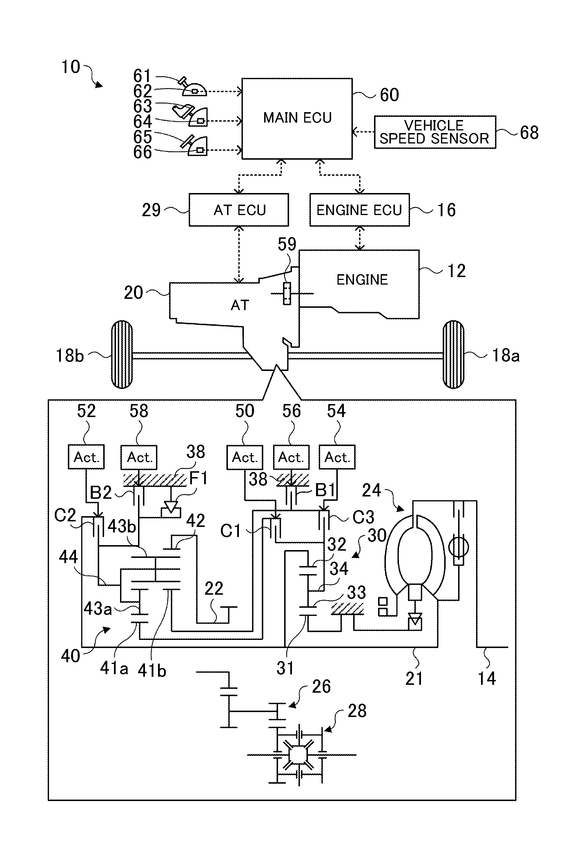
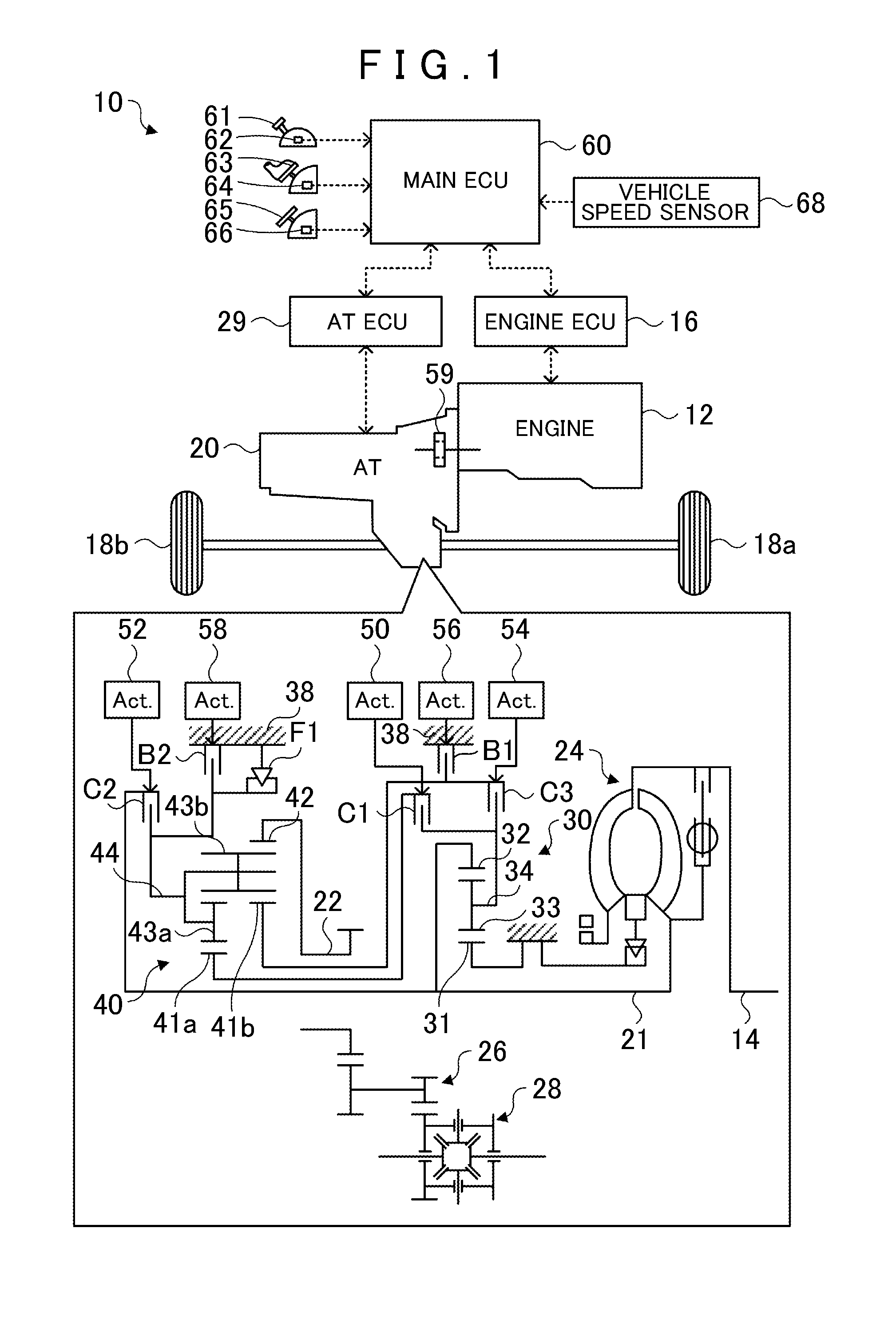
[0012]The automatic transmission control device according to a sixth aspect of the present invention further includes a planetary gear mechanism that has a first rotation element connected to an input shaft side via a first
clutch, a second rotation element connected to the input shaft side via a second
clutch and connected to a case via a second
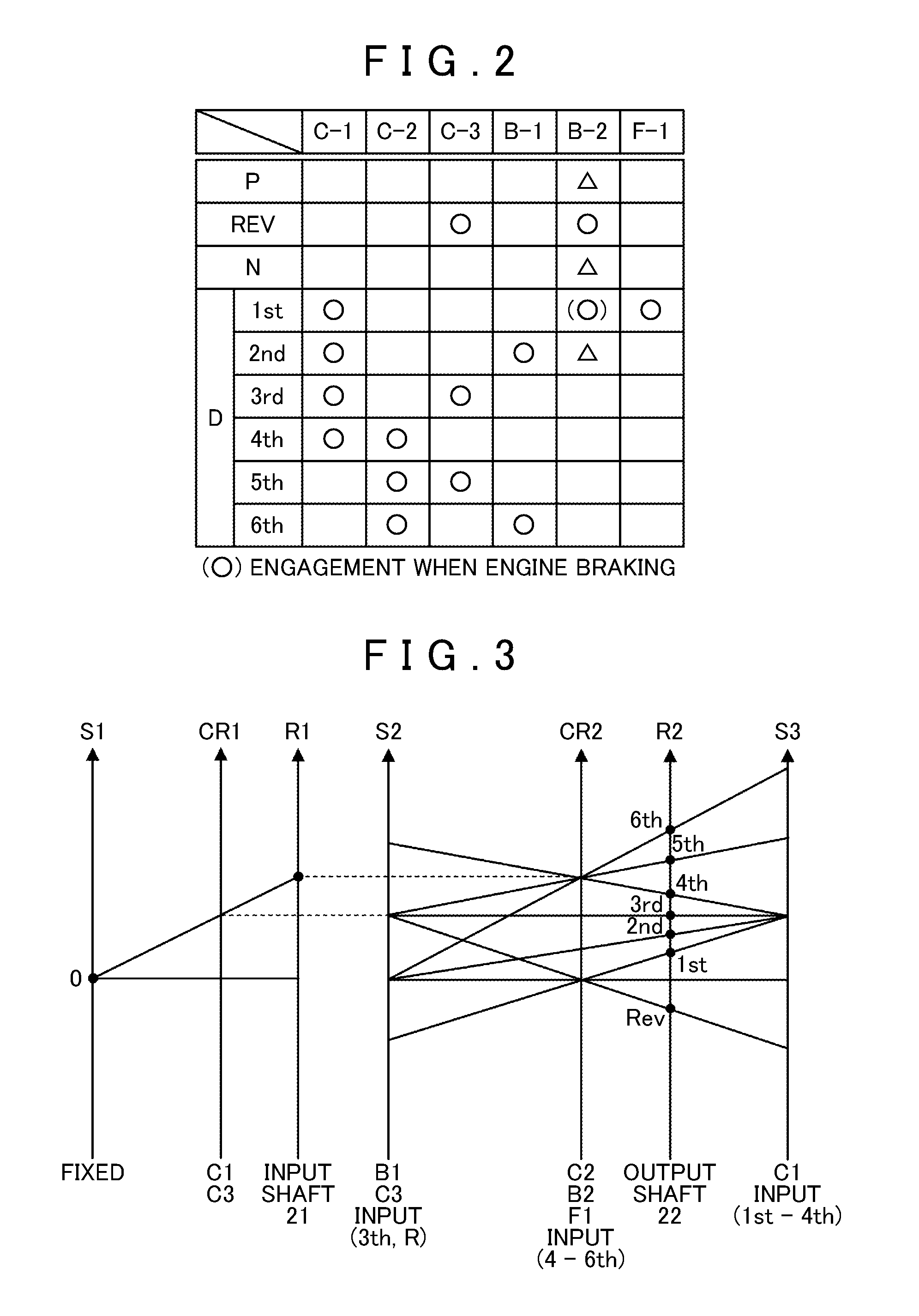
brake, a third rotation element connected to an output shaft side, and a fourth rotation element connected to the input shaft side via a third clutch and connected to the case via a first brake, which have a relation of rotation speed ratios in order of the fourth rotation element, the second rotation element, the third rotation element, and the first rotation element, wherein the first friction engagement element is the second brake, the second friction engagement element is the third clutch, and the third friction engagement element is the first clutch. In the automatic transmission control device of this aspect, while the vehicle is coasting with the shift position at a
neutral position as the non-traveling position, the predetermined standby pressure on the second brake may be released or no engagement pressure may be supplied thereto. When none of the first to third clutches and the first and second brakes are engaged, the third rotation element coupled to the output shaft side of the planetary gear mechanism rotates at a rotation speed depending on the vehicle speed, and the other three rotation elements rotate in a balanced manner independently from the rotation of the third rotation element. However, when the second brake is engaged, the second rotation element to which the second brake is connected is fixed, and thus rotation of the first rotation element accelerates with respect to the rotation speed of the third rotation element. This acceleration in rotation may adversely affect efficiency of the planetary gear mechanism, and may cause dragging of the first clutch connected to the first rotation element. Therefore, while the vehicle is coasting with the shift position at the
neutral position, occurrence of such a
disadvantage is avoided by releasing the standby pressure on the second brake or by supplying no engagement pressure thereto, and traveling resistance can be reduced.
