Guidewire

a technology of guidewires and coating layers, applied in the direction of guide wires, catheters, diagnostic recording/measure, etc., can solve the problems of cracks at the coating layer, impaired flexibility of the guidewire, and peeling of the coating layer, so as to achieve excellent lubricity and prevent cracks

Inactive Publication Date: 2011-10-06
ASAHI INTECC CO LTD
View PDF5 Cites 11 Cited by
  • Summary
  • Abstract
  • Description
  • Claims
  • Application Information

AI Technical Summary

Benefits of technology

[0007]The present invention has been made to solve the foregoing technical problems, and an object of the present invention is to provide a guidewire preventing cracks from being generated at a hy

Problems solved by technology

In this case, flexibility of the guidewire is impaired, and thus the guidewire may perforate a vessel or the like at the time of operating the guidewire.
Also, in a case of bending such a guidewire whose entire layer has be

Method used


Image

  • Guidewire
  • Guidewire
  • Guidewire

Examples


second embodiment

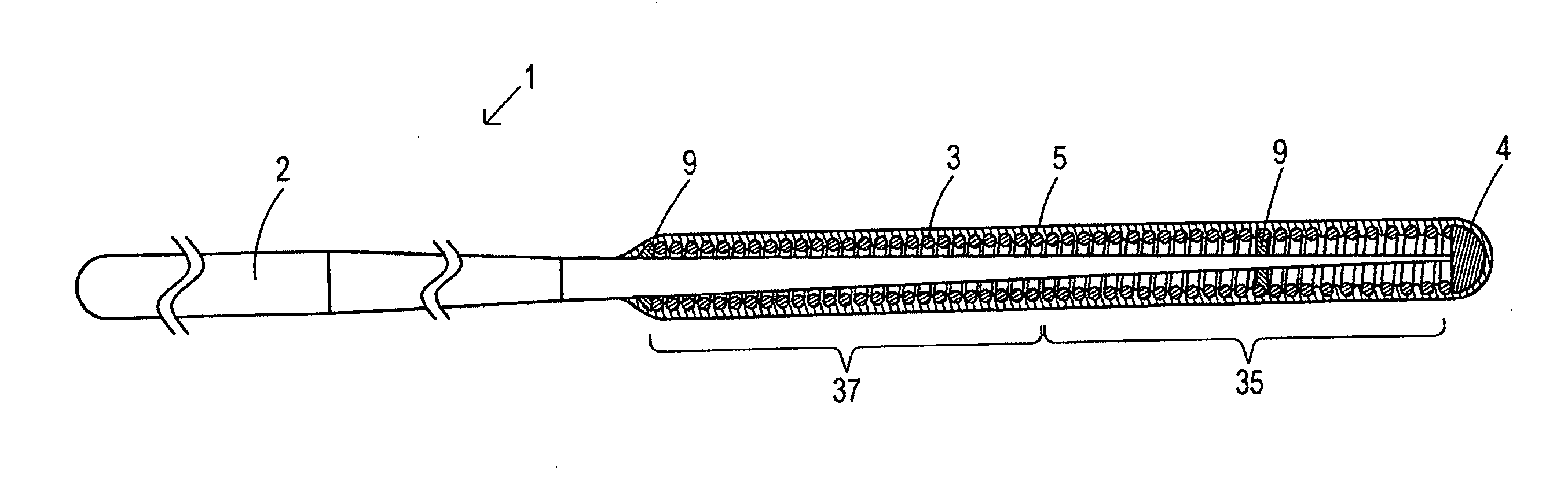
>FIG. 4 is a vertical cross-sectional view showing a guidewire according to the present invention.

[0018]FIG. 5

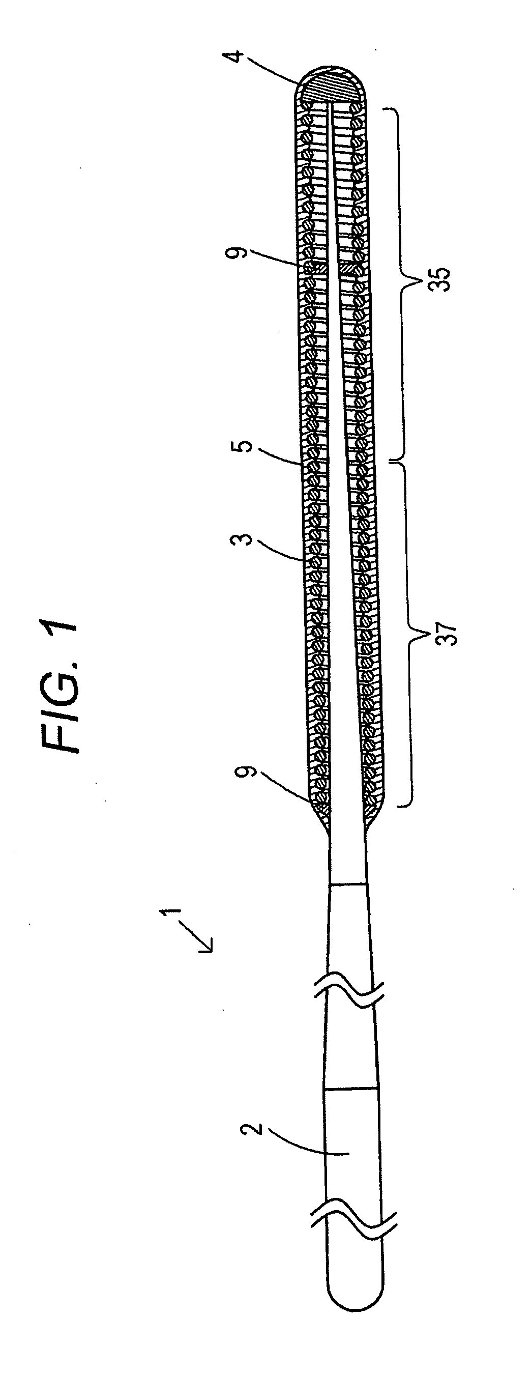
[0019]FIG. 5 is a partially enlarged view of coils of strand constituting a coiled body and a hydrophilic coating agent coated on their surfaces in the second embodiment.

[0020]FIG. 6

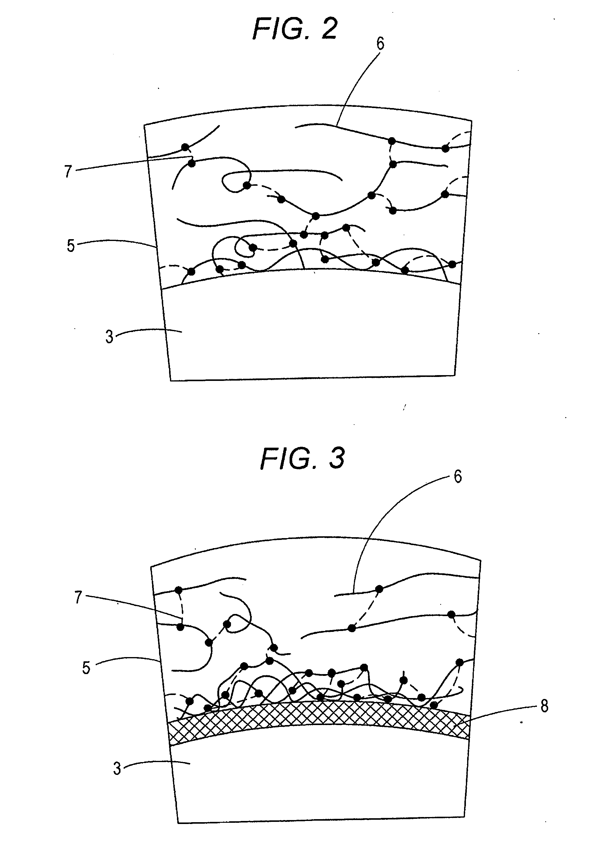
[0021]FIG. 6 is a partially enlarged view showing a modification example of the second embodiment.

DESCRIPTION OF EMBODIMENTS

[0022]Preferred embodiments of the present invention will be described below with reference to the accompanying drawings, in which like reference characters designate similar or identical parts throughout the several views thereof.

[0023] A guidewire according to a first aspect includes a core shaft, a coiled body including coils of strand wound around an outer circumference of the core shaft, and a hydrophilic coating agent coating at least a part of the coiled body, wherein the hydrophilic coating agent is cross-linked by a cross-linking agent, and the degree of cross-linki...

example 1

[0101]First, 2 g of polyvinyl alcohol and 1 g of water-soluble carbodiimide were dissolved in 106 ml of dimethyl formamide as a solvent to prepare a solution of a hydrophilic coating agent (Solution A).

[0102]Next, the most distal portion made of Sn—Ag and the coiled body made of high corrosion resistance stainless steel (SUS316) of the guidewire shown in FIG. 1 were immersed in Solution A.

[0103]Next, the most distal portion and the coiled body of the above guidewire were dried in a drying furnace at 120° C. for 2 hours. By doing so, dimethyl formamide as a solvent was removed, and a cross-linking reaction by water-soluble carbodiimide was accelerated.

[0104]In this manner, the guidewire shown in FIG. 1 coated with the hydrophilic coating agent having a thickness of 1 μm in which the degree of cross-linking decreases in a direction from the side of the coiled body toward the surface side was obtained.

example 2

[0105]First, 2 g of polymer including acid phosphoxy methacrylate containing a phosphoric group on a monomer unit (product name: Phosmer M, produced by Uni-Chemical Co., Ltd.) was dissolved in 100 ml of water as a solvent to prepare Solution B containing a material for a coupling layer.

[0106]Next, 0.5 g of sodium hyaluronate and 1 g of water-soluble carbodiimide were dissolved in 100 ml of water as a solvent to prepare a solution of a hydrophilic coating agent (Solution C).

[0107]Next, the most distal portion and the coiled body of the same guidewire as that in Example 1 were irradiated with 172 nm UV in the atmosphere for 5 minutes with use of a vacuum ultraviolet exposure system (manufactured by Ushio Inc.).

[0108]Next, the portion irradiated with UV was immersed in Solution B. Thereafter, the portion was dried in the drying furnace at 120° C. for 2 hours to remove the solvent. By doing so, the coupling layer was formed on the surfaces of the coiled body and the most distal portion....


PUM

PropertyMeasurementUnit
Hydrophilicityaaaaaaaaaa

Abstract

An object of the present invention is to provide a guidewire preventing cracks from being generated at a hydrophilic coating agent and excellent in lubricity by securing flexibility of the hydrophilic coating agent on its surface side even in a case of using the cross-linked hydrophilic coating agent. The guidewire includes a core shaft, a coiled body provided at a tip portion of the core shaft, a most distal portion fixing a front end of the core shaft and a front end of the coiled body, and a hydrophilic coating agent coating the coiled body and the most distal portion and cross-linked by a cross-linking agent. The degree of cross-linking of the hydrophilic coating agent decreases from a side of the coiled body toward a surface side.

Description

CROSS REFERENCE TO RELATED APPLICATIONS[0001]This application is based on Japanese Patent Application No. 2010-080059 filed with the Japan Patent Office on Mar. 31, 2010, the entire content of which is hereby incorporated by reference.TECHNICAL FIELD[0002]The present invention relates to a guidewire forming a lubricating surface.BACKGROUND ART[0003]Conventionally, as for a guidewire that guides a catheter or the like used by being inserted in a tubular organ such as a vessel, a digestive tract, or a ureter or an intracorporeal tissue for treatment or examination, several kinds each provided on its surface with a hydrophilic coating agent to reduce a friction with the intracorporeal tissue are proposed.[0004]For example, a hydrogel described in Japanese Patent Application Laid-Open No. 2004-215709 is formed by irradiating, with radiation, a solution containing a polymer having high biocompatibility and a polymeric compound cross-linked by radiation.[0005]Also, in a guidewire describe...

Claims


Application Information

Patent Timeline
IPC IPC(8): A61M25/09
CPCA61L31/10A61L31/14A61M25/09A61L2400/10A61M2025/09091A61M2025/09133A61M2025/09083
Inventor SATOZAKI, JUNJI
Owner ASAHI INTECC CO LTD
Why Eureka
Try Eureka