Internal combustion engine ignition controlling apparatus having ignition diagnosing function

a technology of internal combustion engine and ignition control apparatus, which is applied in the direction of machines/engines, braking systems, instruments, etc., can solve the problems of difficult stabilization, practical limit, and unstable fuel concentration in the vicinity, and achieve the effect of achieving engine efficiency

Active Publication Date: 2011-10-13
MITSUBISHI ELECTRIC CORP
View PDF3 Cites 9 Cited by
  • Summary
  • Abstract
  • Description
  • Claims
  • Application Information

AI Technical Summary

Benefits of technology

[0015]The present invention aims to solve such problems as those described above and provide an internal combustion engine ignition controlling apparatus that has an ignition diagnosing function that can detect whether satisfactory spark discharge is performed, and repair faults by notification of abnormality, and that can consequently contribute to environmental protection because target engine efficiency can be achieved.

Problems solved by technology

A difficulty with stratified charge combustion control is stabilizing the concentration of the fuel in the vicinity of the spark plug.
At present, this is difficult to stabilize, and in order to implement stratified charge combustion using existing techniques, it is necessary to adopt either a long electrical discharge method, in which spark discharge is continued until fuel in the vicinity of the spark plug reaches a combustible air-fuel ratio, or a multiple ignition method, in which sparks are repeatedly generated many times.
The above long electrical discharge method is a method in which the ignition coil becomes large and heavy, and there is a practical limit at a discharge time of approximately 2 msec.
However, in the case of multiple ignition systems, each discharging period is often set so as to be short, at approximately 100 to 200 μsec, and if conditions arise in which large capacity components combine on the ignition instruction pathway, ignition interrupting instructions may not be transmitted to the ignition coil as expected, and as a result multiple ignition may not be achieved, leading to deterioration in exhaust gases (emissions) that accompanies deterioration in combustibility, deterioration in fuel consumption that accompanies decline in output, etc., thereby giving rise to problems with regard to environmental protection.
A problem with these techniques is that internal portions of the combustion chamber reach extremely high temperatures during the compression cycle and the fuel ignites spontaneously.
Here too, because it becomes impossible to detect spontaneous ignition if ignition interrupting instructions are not transmitted to the ignition coil as expected, as described above, it is consequently impossible to increase the compression ratio of the engine, leading to deterioration in fuel consumption, etc., due to deterioration in thermal efficiency, and compounding the problems with regard to environmental protection.
If intermittent interference from the power supply system wiring is generated in the ignition instruction supply line, then ignition due to passage and interruption of electric current to the ignition coil may be repeated at a timing that is different than the intended ignition timing regardless of the ignition instruction, and in such cases, there is also a possibility that this may lead to damage to the engine.

Method used


Image

  • Internal combustion engine ignition controlling apparatus having ignition diagnosing function
  • Internal combustion engine ignition controlling apparatus having ignition diagnosing function
  • Internal combustion engine ignition controlling apparatus having ignition diagnosing function

Examples


embodiment 1

[0025]Embodiment 1 of the present invention will now be explained with reference to the drawings.

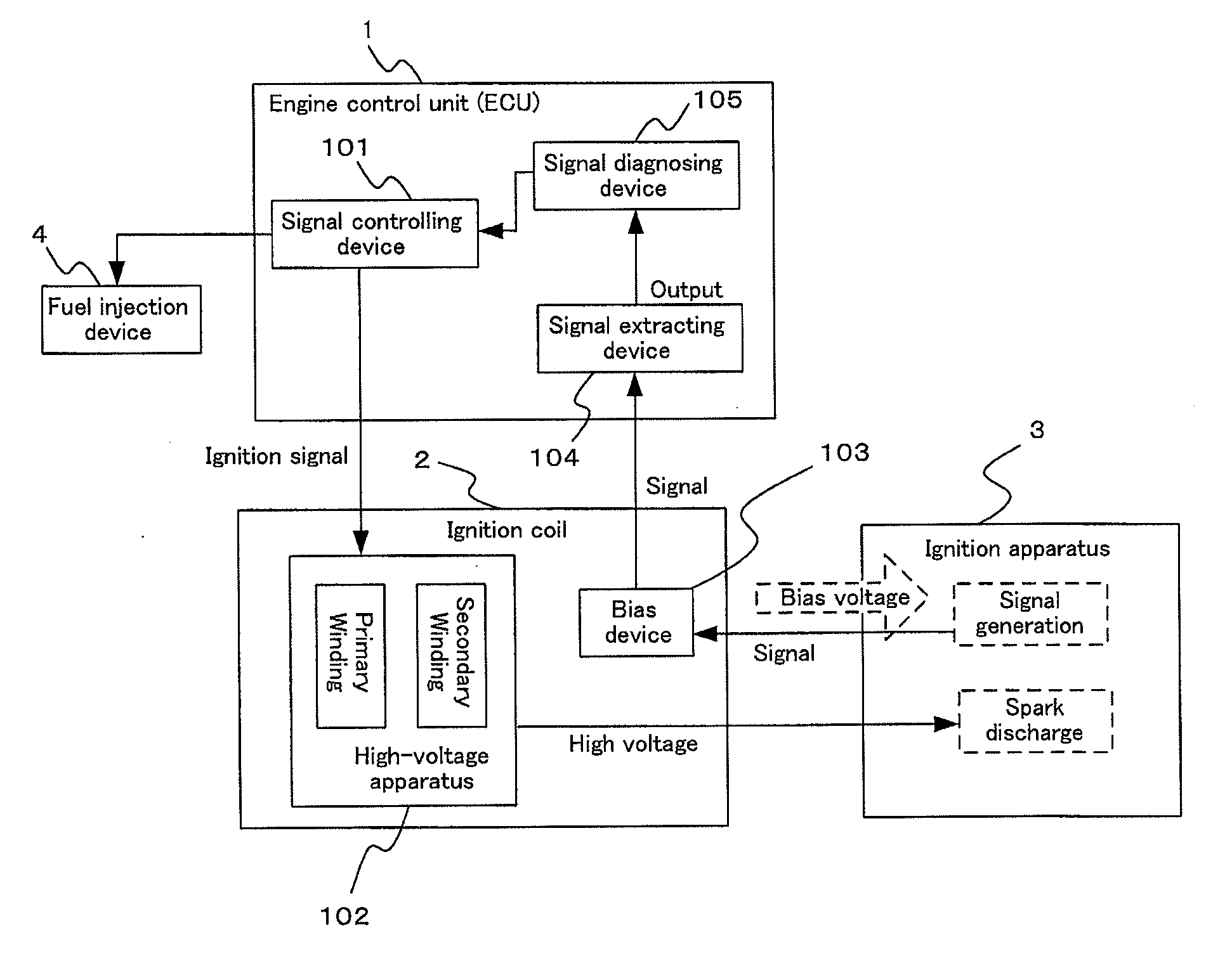
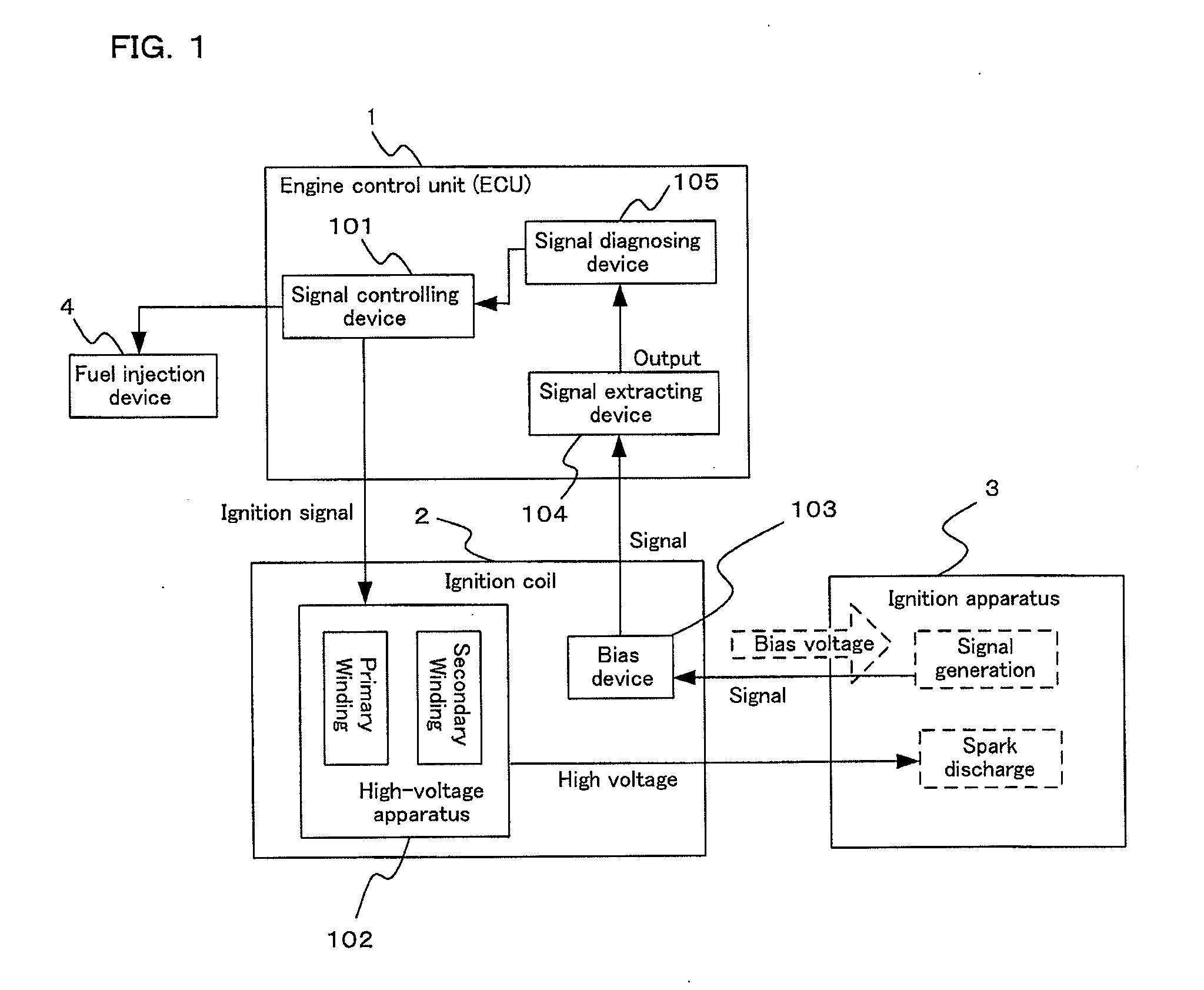
[0026]FIG. 1 is a diagram that shows an overall configuration of an apparatus according to the present invention, and 1 represents a controlling apparatus that controls input and output of various kinds of signal, generally called an engine control unit (ECU). 2 represents an ignition coil, and 3 represents an ignition apparatus (a spark plug), an ignition controlling apparatus being configured by these three apparatuses. 4 represents a fuel injection device. A signal controlling device 101 inside the ECU 1 generates an ignition signal which is an instruction signal for operating the ignition coil 2. When the ignition signal is in a “High” state, the ignition coil 2 commences energy accumulation by an electric current (a primary current) flowing through a primary winding inside the ignition coil, and the ignition coil 2 generates a high voltage of approximately 30 kV, for example, in an ...

embodiment 2

[0045]A method in which misfire diagnosis results from a misfire detecting means are added to the ignition diagnosing method that is shown in Embodiment 1 will be explained based on FIG. 4. Because the flowchart that is shown in FIG. 4 is basically similar to the flowchart that is shown in FIG. 3, differences from FIG. 3 will be focused on and explained.

[0046]If it is determined at S306 in FIG. 4 that value A is greater than or equal to the comparison value P3 (N), then determine that there may be ignition failure, and proceed to S401. Here, if it is determined, using the determination of the misfire detecting means, that a misfire has occurred (Y), then the possibility of ignition failure is deemed to be higher, proceed to S307, increase the counter value of CNT1, and proceed to S315. On the other hand, if a misfire has not occurred at S401 (N), then a conflict has occurred between the ignition diagnosis and the misfire diagnosis, in other words, determine that it is very likely th...

embodiment 3

[0049]Embodiment 3 will be explained based on FIGS. 5 and 6. In Embodiment 1, for microcomputer computational load reduction inside the ECU 1, it was determined that multiple ignition is abnormal if a signal generation position C is less than a comparison level P5, that is, retarded, but multiple ignition diagnosis can be performed more accurately using parameters such as an impulse signal generation count such as 501 in FIG. 5 that is generated together with the igniting operation inside the multiple ignition zone and an instruction count and timing of multiple ignition. A specific method will be explained.

[0050]With reference to the timing chart in FIG. 5, comparison levels 502 (P10) and 503 (P11) relative to the signal 202 and a multiple ignition diagnostic zone 504 are set, and an impulse signal count is counted (CNT3) in accordance with the flowchart in FIG. 6A.

[0051]First, at S551, check whether the diagnostic zone is present. The diagnostic zone (FIG. 5, 504, a fourth detecti...


PUM

PropertyMeasurementUnit
discharge timeaaaaaaaaaa
voltageaaaaaaaaaa
constant voltageaaaaaaaaaa

Abstract

An ignition controlling apparatus is provided that can diagnose a state of spark discharge in an internal combustion engine, and perform appropriate actions based on the diagnostic results.In the internal combustion engine ignition controlling apparatus, a controlling apparatus has a signal extracting device that extracts an ion current that is generated together with combustion of a combustible gas mixture inside a combustion chamber by a spark discharge of an ignition apparatus based on an ignition signal of an ignition coil, includes a signal diagnosing device that sets a predetermined detection zone from a period in a single stroke of an internal combustion engine from a first spark discharge commencement until after a last spark discharge completion, and that determines an ignition state based on parameters included in the signal extracted in this detection zone, and controls the internal combustion engine in response to this ignition state.

Description

BACKGROUND OF THE INVENTION[0001]1. Field of the Invention[0002]The present invention relates to an igniting operation that ignites fuel during running of an internal combustion engine, and relates to an ignition controlling apparatus that determines whether this igniting operation is being implemented normally.[0003]2. Description of the Related Art[0004]In recent years, problems of environmental protection and fuel depletion have been raised, and responding thereto has also become a major task in the automotive industry. In response thereto, many techniques have been developed that attempt to raise internal combustion engine efficiency to a maximum. One of these is a stratified charge combustion control method in which flow is controlled such that fuel is distributed only in a vicinity of a spark ignition source (a spark plug), and combustion is generated using a quantity of fuel that is significantly reduced relative to volume of air that is charged inside an internal combustion ...

Claims


Application Information

Patent Timeline
Patent Type & Authority Applications(United States)
IPC IPC(8): G01L23/22
CPCF02P2017/125F02P17/12
Inventor TANAYA, KIMIHIKO
Owner MITSUBISHI ELECTRIC CORP
Why Eureka
Try Eureka