
Nonmagnetic Material Particle-Dispersed Ferromagnetic Material Sputtering Target

Active Publication Date: 2011-10-13
JX NIPPON MINING& METALS CORP
View PDF8 Cites 31 Cited by
  • Summary
  • Abstract
  • Description
  • Claims
  • Application Information

AI Technical Summary

Benefits of technology

[0014]Moreover, although the leakage magnetic flux can be improved by thinning the thickness of the target, in this case the target life is shortened, and costs will increase since the target needs to be replaced frequently.
[0047]In addition, as a result of achieving high densification, there is also an advance in that the generation of particles can be reduced.

Problems solved by technology

Generally speaking, if the foregoing magnetron sputtering device is used to sputter a nonmagnetic material particle-dispersed ferromagnetic material sputtering target, since much of the magnetic flux from the magnet will pass through the target, which is a ferromagnetic material, the leakage magnetic flux will decrease, and there is a major problem in that a discharge does not occur during the sputtering, or, the discharge is unstable even if a discharge does occur.
Nevertheless, these methods are not substantial solutions since the intended granular film cannot be obtained.
Moreover, although the leakage magnetic flux can be improved by thinning the thickness of the target, in this case the target life is shortened, and costs will increase since the target needs to be replaced frequently.

Method used


Image

  • Nonmagnetic Material Particle-Dispersed Ferromagnetic Material Sputtering Target
  • Nonmagnetic Material Particle-Dispersed Ferromagnetic Material Sputtering Target
  • Nonmagnetic Material Particle-Dispersed Ferromagnetic Material Sputtering Target

Examples


example 1

Comparative Example 1

[0067]In Example 1, Co powder with an average particle size of 3 μm, SiO2 powder with an average particle size of 1 μm, and Co—Cr spherical powder with a diameter within the range of 50 to 150 μm and containing 60 mol % of Cr were prepared as the raw material powders. These powders were respectively weighed at a weight ratio of Co powder 68.91 wt %, SiO2 powder 8.28 wt %, and Co—Cr spherical powder 22.81 wt % to achieve a target composition of 77.5 Co-14.5 Cr-8 SiO2 (mol %). Subsequently, Co powder and SiO2 powder were placed in a ball mill pot with a capacity of 10 liters together with zirconia balls as the grinding medium, and rotated and mixed for 20 hours. The obtained mixed powder and the Co—Cr spherical powder were mixed for 10 minutes in a sun-and-planet motion-type mixer with a ball capacity of approximately 7 liters.

[0068]This mixed powder was filled in a carbon mold, and hot pressed in a vacuum atmosphere under the following conditions; namely, tempera...

example 2

Comparative Example 2

[0078]In Example 2, Co powder with an average particle size of 3 μm, Pt powder with an average particle size of 2 μm, SiO2 powder with an average particle size of 1 μm, and Co—Cr spherical powder with a diameter within the range of 50 to 150 μm and containing 40 mol % of Cr were prepared as the raw material powders.

[0079]These powders were respectively weighed at a weight ratio of Co powder 26.62 wt %, Pt powder 39.16 wt %, SiO2 powder 6.03 wt %, and Co—Cr spherical powder 28.19 wt % to achieve a target composition of 60 Co-16 Cr-16 Pt-8 SiO2 (mol %).

[0080]Subsequently, the Co powder, Pt powder, and SiO2 powder were placed in a ball mill pot with a capacity of 10 liters together with zirconia balls as the grinding medium, and rotated and mixed for 20 hours. The obtained mixed powder and the Co—Cr spherical powder were mixed for 10 minutes in a sun-and-planet motion-type mixer with a ball capacity of approximately 7 liters.

[0081]This mixed powder was filled in a ...

example 3

Comparative Example 3

[0091]In Example 3, Co powder with an average particle size of 3 μm, Pt powder with an average particle size of 2 μm, B powder with an average particle size of 10 μm, TiO2 powder with an average particle size of 0.5 μm, and Co—Cr spherical powder with a diameter within the range of 100 to 200 μm and containing 40 mol % of Cr were prepared as the raw material powders.

[0092]These powders were respectively weighed at a weight ratio of Co powder 22.89 wt %, Pt powder 39.99 wt %, B powder 0.4 wt %, TiO2 powder 7.94 wt %, and Co—Cr spherical powder 28.78 wt % to achieve a target composition of 56 Co-16.5 Cr-16.5 Pt-3 B-8 TiO2 (mol %).

[0093]Subsequently, the Co powder, Pt powder, B powder, and TiO2 powder were placed in a ball mill pot with a capacity of 10 liters together with zirconia balls as the grinding medium, and rotated and mixed for 20 hours. The obtained mixed powder and the Co—Cr spherical powder were mixed for 10 minutes in a sun-and-planet motion-type mixe...


PUM

PropertyMeasurementUnit
Fractionaaaaaaaaaa
Fractionaaaaaaaaaa
Fractionaaaaaaaaaa

Abstract

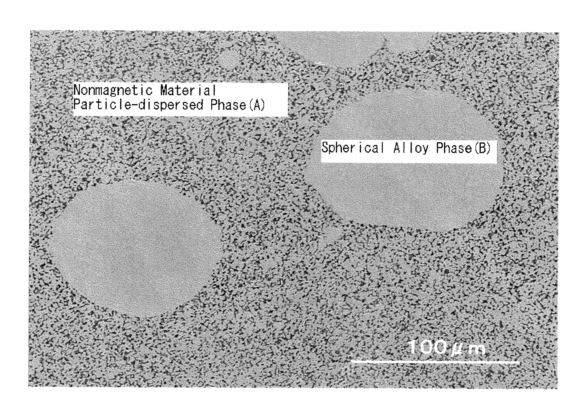
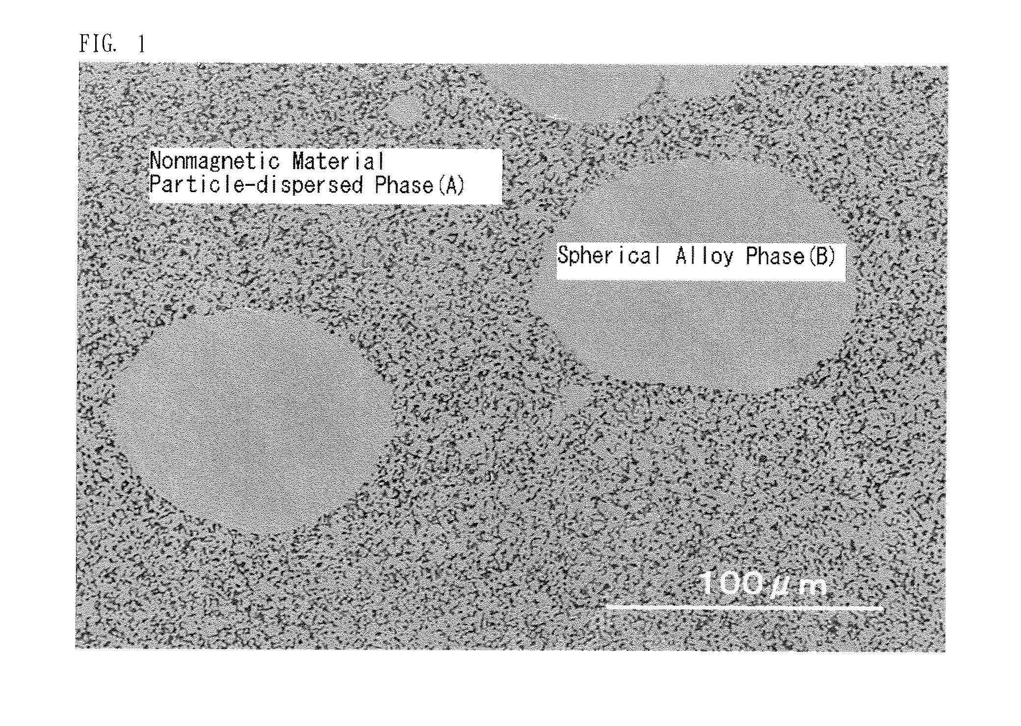
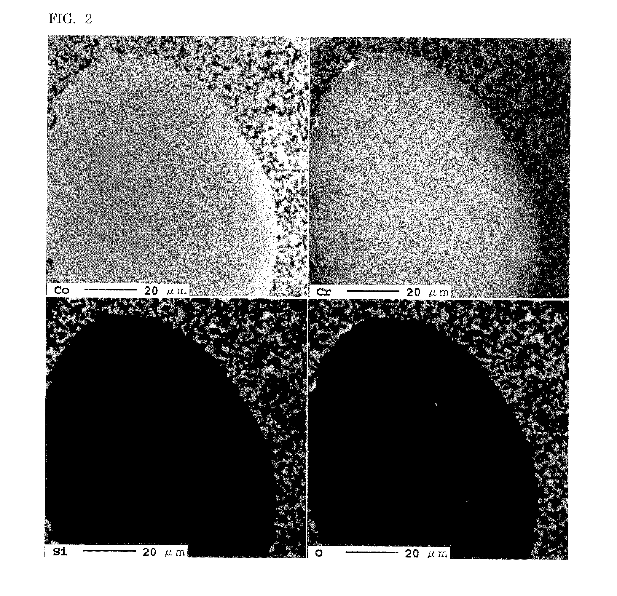
A nonmagnetic material particle-dispersed ferromagnetic material sputtering target comprising a mixture of an alloy containing 5 mol % or more and 20 mol % or less of Cr, 5 mol % or more and 30 mol % or less of Pt, and Co as the remainder thereof, and nonmagnetic material particles, wherein the structure of the target includes a phase (A) in which the nonmagnetic material particles are uniformly micro-dispersed in the alloy, and a spherical alloy phase (B) dispersed in the phase (A) in which the ratio of its volume in the target is 4% or more and 40% or less. Obtained is a nonmagnetic material particle-dispersed ferromagnetic material sputtering target capable of improving the leakage magnetic flux to obtain a stable electrical discharge with a magnetron sputtering device, and which has high density and generates few particles during sputtering.

Description

TECHNICAL FIELD[0001]The present invention relates to a nonmagnetic material particle-dispersed ferromagnetic material sputtering target for use in the deposition of a magnetic thin film of a magnetic recording medium, and particularly of a granular magnetic recording film of a hard disk adopting the perpendicular magnetic recording system, and to a sputtering target with a leakage magnetic flux which is able to obtain stable electrical discharge when sputtered with a magnetron sputtering device, and which has high density and generates few particles during sputtering.BACKGROUND ART[0002]In the field of magnetic recording, technology has been developed for improving the magnetic property by uniformly micro-dispersing nonmagnetic materials in a magnetic thin film. As one example thereof, with a hard disk recording medium adopting the perpendicular magnetic recording system, a granular film is adopted for blocking or weakening the magnetic interaction between magnetic particles in the...

Claims


Application Information

Patent Timeline
IPC IPC(8): C23C14/14
CPCB22F2998/00C22C32/0026C22C32/0052C22C32/0068C23C14/3414H01F41/183B22F2303/01B22F2301/15
Inventor SATO, ATSUSHI
Owner JX NIPPON MINING& METALS CORP
Learn More