

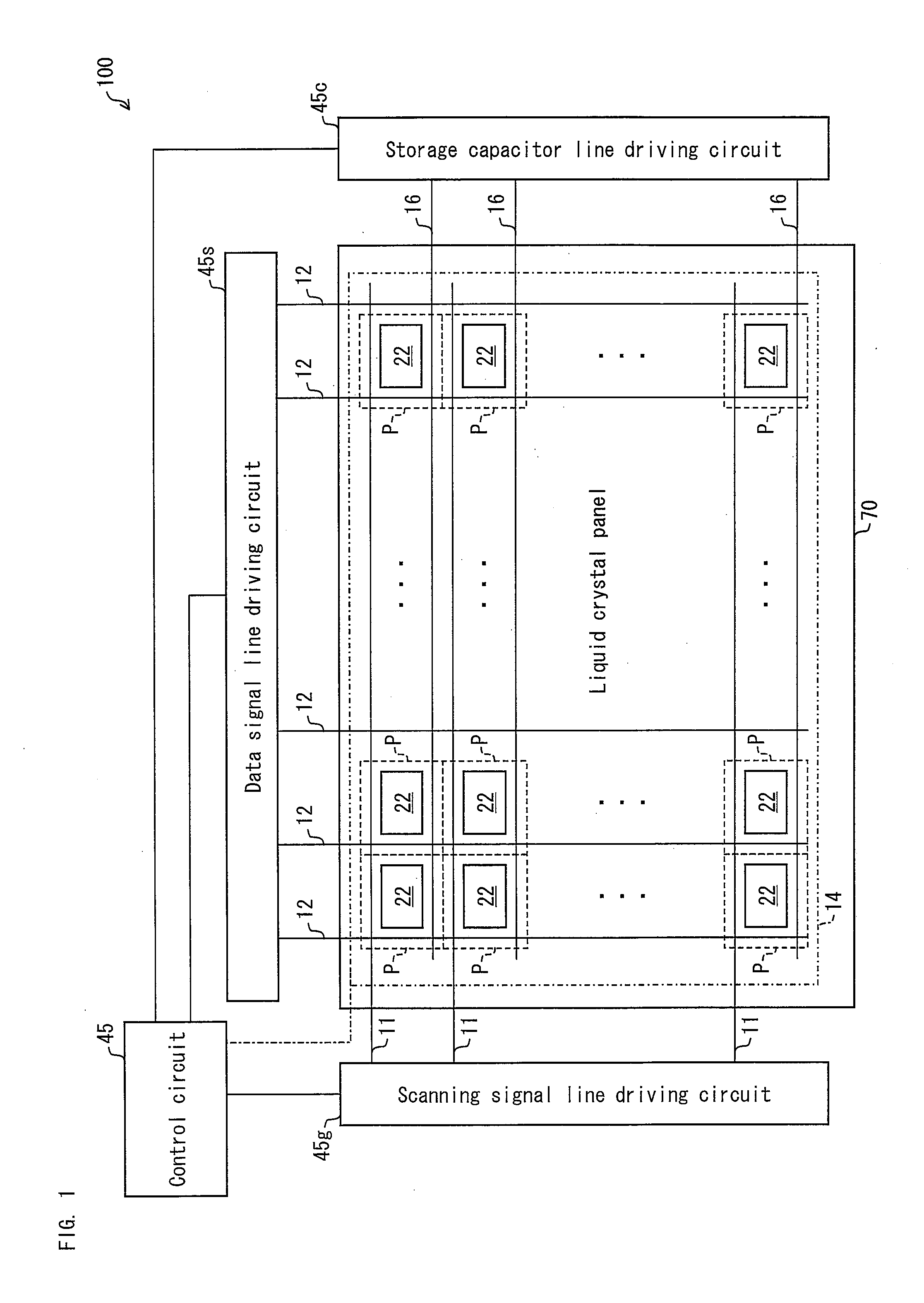
Active matrix substrate manufacturing method and liquid crystal display device manufacturing method
a technology of active matrix substrate and manufacturing method, which is applied in the direction of semiconductor devices, electrical devices, instruments, etc., can solve the problems of low heat resistance of al alone, insufficient resolution of exposure devices, and inability to resolve line-and-space patterns, so as to reduce the number of steps, reduce the manufacturing cost of active matrix substrate, and reduce the effect of manufacturing cos
- Summary
- Abstract
- Description
- Claims
- Application Information
AI Technical Summary
Benefits of technology
Problems solved by technology
Method used
Image

Examples
embodiment 1
Modification of Embodiment 1
[0135]The active matrix substrate of Embodiment 1, which is manufactured in the streamlined manner, employs TN liquid crystal. By modifying the shape of the pixel electrode, the present invention is also effective in vertical alignment liquid crystal, which provides a wide viewing angle. This will be described below as a part of Embodiment 1.
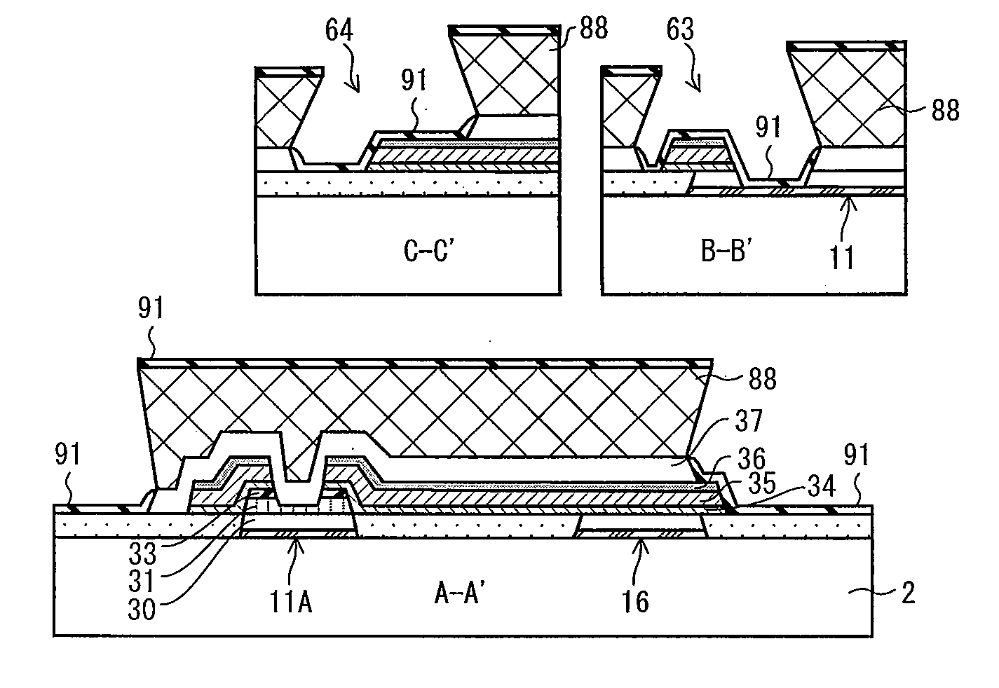
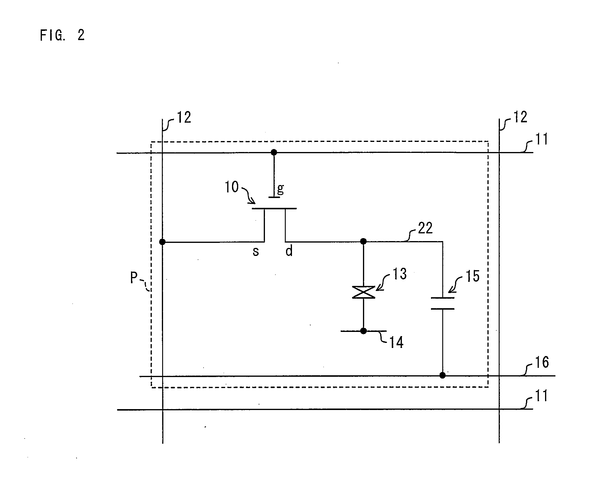
[0136]Alignment regulation means which can be formed in an active matrix substrate 71 included in a vertical alignment liquid crystal panel is a slit provided in a pixel electrode or a projection provided on the pixel electrode. Now, this basic configuration is applied to the active matrix substrate 71 of Embodiment 1. Then, as shown in (a) of FIG. 7 and (a) of FIG. 8, pixel electrodes 22-1 though 22-4, which are transparent and electrically conductive and are shaped in a plurality of stripes, are connected with a drain electrode 21 via a storage electrode 72. Further, in order to provide multi domain, the pixel elect...
embodiment 2
Modification of Embodiment 2
[0163]The active matrix substrate of Embodiment 2, which is manufactured in the streamlined manner, employs TN liquid crystal. By modifying the shape of the pixel electrode, the present invention is also effective in IPS liquid crystal and vertical alignment liquid crystal, each of which provides a wide viewing angle. This will be described below as a part of Embodiment 2.
[0164]Here, a basic structure including a pair of (i) a counter electrode formed on an active matrix substrate 71 and (ii) a pixel electrode formed so as to be away from the counter electrode by a predetermined distance is applied to the active matrix substrate 71 of Embodiment 2. Then, as shown in (a) of FIG. 13 and (a) of FIG. 14, a plurality of counter electrodes 16A and a plurality of pixel electrodes 21A are formed so as to be away from each other by a predetermined distance. The counter electrodes 16A, which are shaped in stripes, are branched from a storage capacitor line 16 withi...
embodiment 3
Modification of Embodiment 3
[0193]The active matrix substrate of Embodiment 3, which is manufactured in the streamlined manner, employs TN liquid crystal. By modifying the shape of the pixel electrode, the present invention is also effective in IPS liquid crystal and vertical alignment liquid crystal, each of which provides a wide viewing angle. This will be described below as a part of Embodiment 3.
[0194]Here, a basic structure of an IPS liquid crystal panel is applied to the active matrix substrate 71 of Embodiment 3. Then, as shown in (a) of FIG. 19 and (a) of FIG. 20, a plurality of counter electrodes 16A and a plurality of pixel electrodes 21A are formed so as to be away from each other by a predetermined distance. The counter electrodes 16A, which are shaped in stripes, are made of a transparent electrically conductive layer formed in an opening provided in a passivation insulative layer 37 on a transparent insulative layer 60. The pixel electrodes 21A, which are shaped in str...
PUM
 Abstract
Description
Claims
Application Information