Method and apparatus to generate angiographic magnetic resonance images

a technology of angiographic magnetic resonance and generating method, which is applied in the field of methods and apparatus to generate angiographic magnetic resonance images, can solve the problems of severe limitation of fisp imaging, loss of marking, and strong limitation of the volume within which the inflow process can be acquired

Active Publication Date: 2011-10-13
SIEMENS HEALTHCARE GMBH
View PDF1 Cites 11 Cited by
  • Summary
  • Abstract
  • Description
  • Claims
  • Application Information

AI Technical Summary

Benefits of technology

[0031]The magnetic resonance system can be designed to implement the method described in the preceding. The magnetic resonance system therefore has the same advantages as the method described in the preceding.

Problems solved by technology

This loss of the marking takes place particularly quickly in FLASH imaging, but also represents a severe limitation in FISP imaging (Fast Imaging with Steady State Recession).
However, the volumes within which the inflow process can be acquired is hereby strongly limited.

Method used


Image

  • Method and apparatus to generate angiographic magnetic resonance images
  • Method and apparatus to generate angiographic magnetic resonance images
  • Method and apparatus to generate angiographic magnetic resonance images

Examples


Embodiment Construction

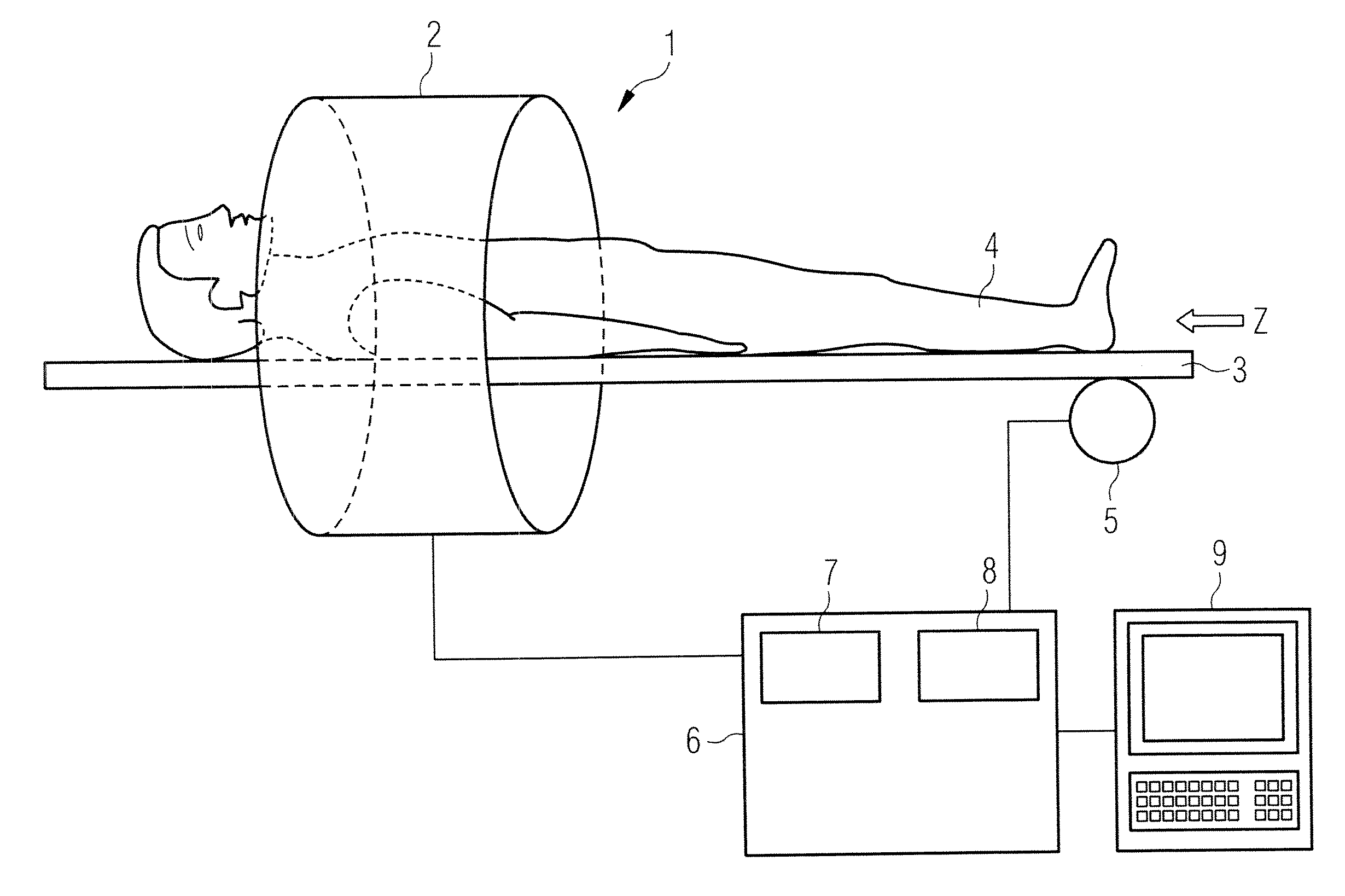
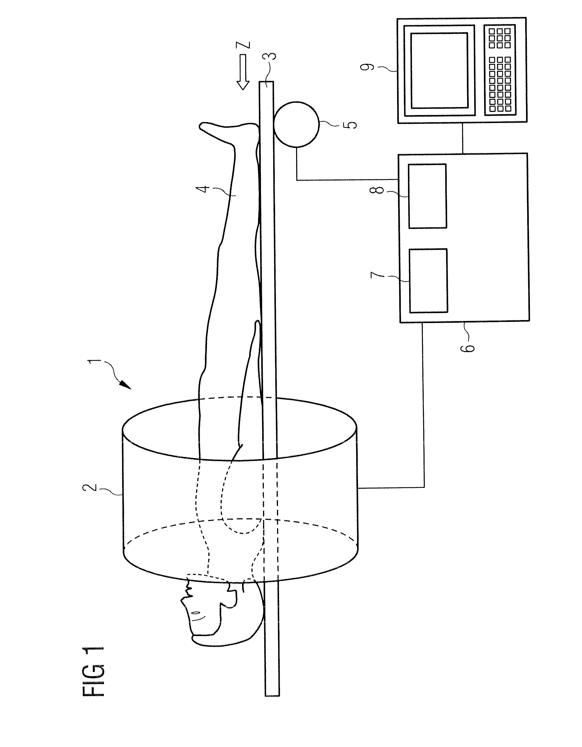
[0044]FIG. 1 shows a magnetic resonance system 1 with which a series of temporally successive angiographic magnetic resonance images can be generated according to the invention and which achieves an improved image quality across the entire series with a higher contrast vessel representation. The magnetic resonance system 1 has a magnet 2 to generate a polarization field B0. An examination subject 4 arranged on a bed 3 is driven with the aid of a drive 5 into the middle of the magnet 2, where an acquisition of the magnetic resonance signals from an examination region is conducted by radiating radio-frequency pulses and switching gradients. How magnetic resonance images can be generated in a pulse sequence via a series of radio-frequency pulses and switching of gradients is basically familiar to the man skilled in the art and is not described in detail here.

[0045]The magnetic resonance system 1 is connected with a central control unit 6 with which the magnetic resonance system 1 is co...


PUM


Abstract

In a magnetic resonance system and operating method to generate a series of temporally successive angiographic magnetic resonance images of an examination region, a series with a predetermined number of flip angles is established. The first flip angle at the beginning of the series is smaller than the last flip angle at the end of the series, and an arbitrary flip angle is greater than or equal to the preceding flip angle in the series. First and second magnetic resonance data are determined by acquiring a predetermined number of partial segments of k-space belonging to the first and second magnetic resonance data. Each partial segment is acquired over a respective first or second time interval and respectively has a series of components. Each component is acquired according to a gradient echo method with a flip angle that exists at a position in the series of flip angles, which position corresponds to the component. A fluid flowing into the examination region is given a first predetermined spin marking at the beginning of the first time intervals and a second predetermined spin marking, different than the first spin marking, at the beginning of the second time intervals. The series of temporally successive angiography magnetic resonance images is generated by combining the first and second magnetic resonance data.

Description

BACKGROUND OF THE INVENTION[0001]1. Field of the Invention[0002]The present invention concerns a method and a magnetic resonance system to generate a series of temporally successive angiographic magnetic resonance images of an examination region, in particular a contrast agent-free generation of temporally successive angiographic magnetic resonance images.[0003]2. Description of the Prior Art[0004]Various methods for contrast agent-free dynamic magnetic resonance angiography, what is known as non-contrast enhanced (NCE) magnetic resonance angiography, are known in the prior art. In these methods, blood flowing in is marked with the aid of what is known as a spin labeling method and imaged during the inflow into an examination region, known as an imaging volume of interest (VOI).[0005]To mark and depict the inflowing blood, the same examination region is typically acquired twice with different labeling. In the prior art the methods FAIR (Flow-Sensitive Alternating Inversion Recovery)...

Claims


Application Information

Patent Timeline
Patent Type & Authority Applications(United States)
IPC IPC(8): A61B5/055
CPCA61B5/0263A61B5/055A61B5/7285G01R33/5635G01R33/5613G01R33/5614G01R33/4826
Inventor SCHMITT, PETER
Owner SIEMENS HEALTHCARE GMBH
Why Eureka
Try Eureka