Deployable solar panel system

Inactive Publication Date: 2011-10-20
GENERAL ELECTRIC CO
View PDF2 Cites 62 Cited by
  • Summary
  • Abstract
  • Description
  • Claims
  • Application Information

AI Technical Summary

Benefits of technology

[0010]The inventors have recognized that a lightweight, flexible PV module that does not require an expensive racking system will result in the lowest installed cost, particularly for a low slope commercial rooftop.
[0011]The inventors have also recognized that PV modules that are installed on a low slope roof at a tilt angle of about 2-5 degrees and do not self-shade provide the highest per area power yield.
[0012]In accordance with the invention, the costs and complexity

Problems solved by technology

On roofs of commercial buildings, which usually have no or low slope, modules are mounted at a desired tilt angle using a dedicated substructure, which adds additional weight to the roof.
In addition, many residential and commercial buildings, particularly in the western, and southern parts of the United States, are not designed to handle snow loading and are structurally weaker.
Many warehouses and large box stores are not equipped to handle heavy solar systems.
These additional weight loads can be substantial.
In addition, additional wind loads emerge almost always when additional

Method used


Image

  • Deployable solar panel system
  • Deployable solar panel system
  • Deployable solar panel system

Examples


Example

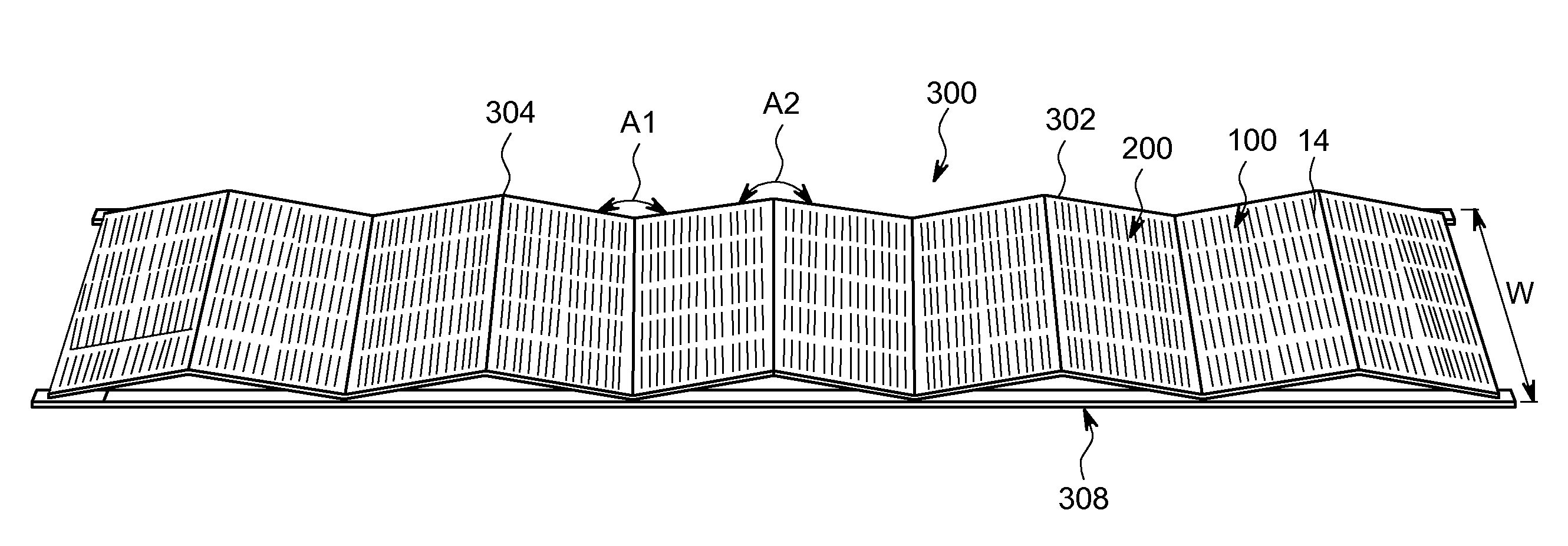
[0023]While the principles of the invention can be applied to different semiconductor based PV modules, the description that follows applies to one unique type of PV module that is based on a very thin elongate solar cell that is also bi-facial and results in a semi-flexible-to-flexible module assembly.

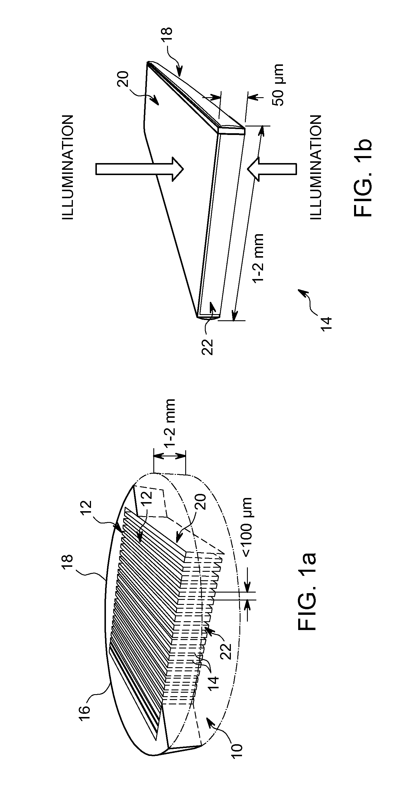
[0024]There are known processes that can produce elongate solar cells. As used herein, the term “elongate solar cell” refers to a solar cell of generally parallelepiped form and having a high aspect ratio in that its length is substantially greater (typically some tens to hundreds of times larger) than its width. The thickness of an elongate solar cell is largely immaterial to the present invention, but is typically four to one hundred times smaller than the width of the cell. The length and width of a solar cell define the maximum available active surface area for power generation (the active “face” or “faces” of the solar cell), whereas the length and thickness of a solar cell defin...


PUM


Abstract

A deployable solar panel system includes a plurality of solar cell panels that are mechanically and electrically coupled to each other prior to shipment to an installation site, folded in a stacking arrangement within a packaging container for shipment to the installation site, and then unfolded to deploy the solar cell panels at a desired tilt angle during installation at the installation site. In one embodiment, the solar cell panels are mechanically coupled to each other using a hinge assembly, such as a hinge bracket and hinge pin. Each solar cell panel system is electrically coupled to each other using a series string. The series string may be electrically coupled to a DC-DC converter and/or a DC-AC inverter.

Description

BACKGROUND OF THE INVENTION[0001]1. Field of the Invention[0002]The invention relates to the installation of solar cell panels, and in particular to a system and method of installing solar cell panels on a low slope surface, such as a rooftop of a commercial building, and the like.[0003]2. Description of the Related Art[0004]Currently, there is approximately 11 billion square meters of commercial rooftop surface available worldwide. Tapping even a small fraction of this potential would make a significant impact on the world's energy needs.[0005]On roofs of commercial buildings, which usually have no or low slope, modules are mounted at a desired tilt angle using a dedicated substructure, which adds additional weight to the roof. Mounting a solar array on existing residential buildings does not normally pose a problem with additional weight because the typical residential substructure is built for heavy snow and is capable of supporting the framed solar modules and mounting structure...

Claims


Application Information

Patent Timeline
IPC IPC(8): H01L31/045H02S30/20
CPCF24J2/36F24J2/523F24J2002/5486Y02B10/12Y02B10/20H02S20/24Y02E10/47H01L31/048H01L31/0512H02S40/22H02S30/20Y02E10/50Y02E10/52F24S20/50F24S2030/16F24S25/10H02S20/30F24S20/55Y02B10/10
Inventor KORMAN, CHARLES STEVENJOHNSON, NEIL ANTHONY
Owner GENERAL ELECTRIC CO
Why Eureka
Try Eureka