
Controlled Alignment in Polymeric Solar Cells

a solar cell and polymer technology, applied in the field of material science, can solve the problems of low efficiency achieved by these solar cells, and achieve and achieving the effect of improving the efficiency of solar cells

Inactive Publication Date: 2011-10-20
RGT UNIV OF CALIFORNIA
View PDF3 Cites 17 Cited by
  • Summary
  • Abstract
  • Description
  • Claims
  • Application Information

AI Technical Summary

Benefits of technology

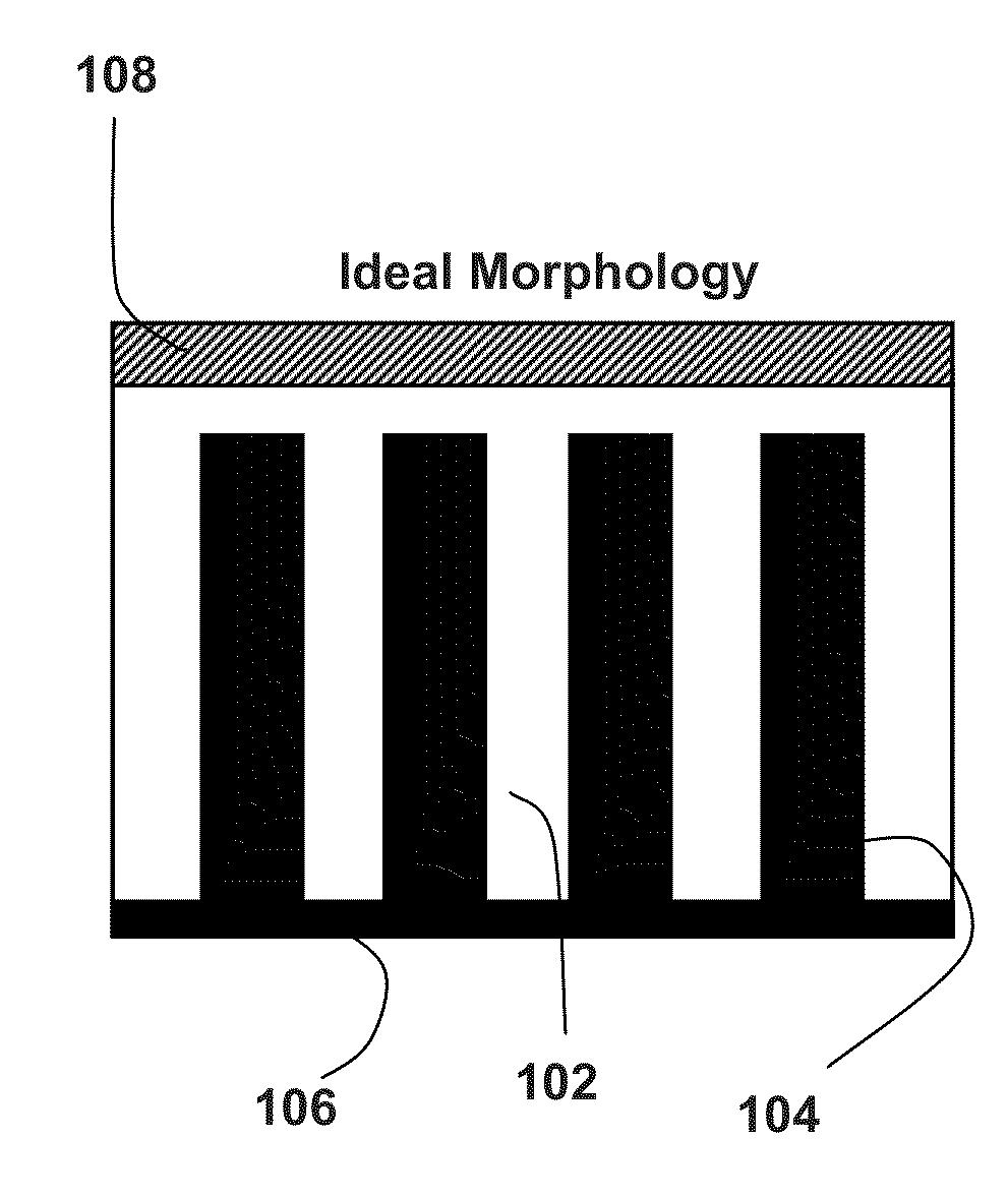
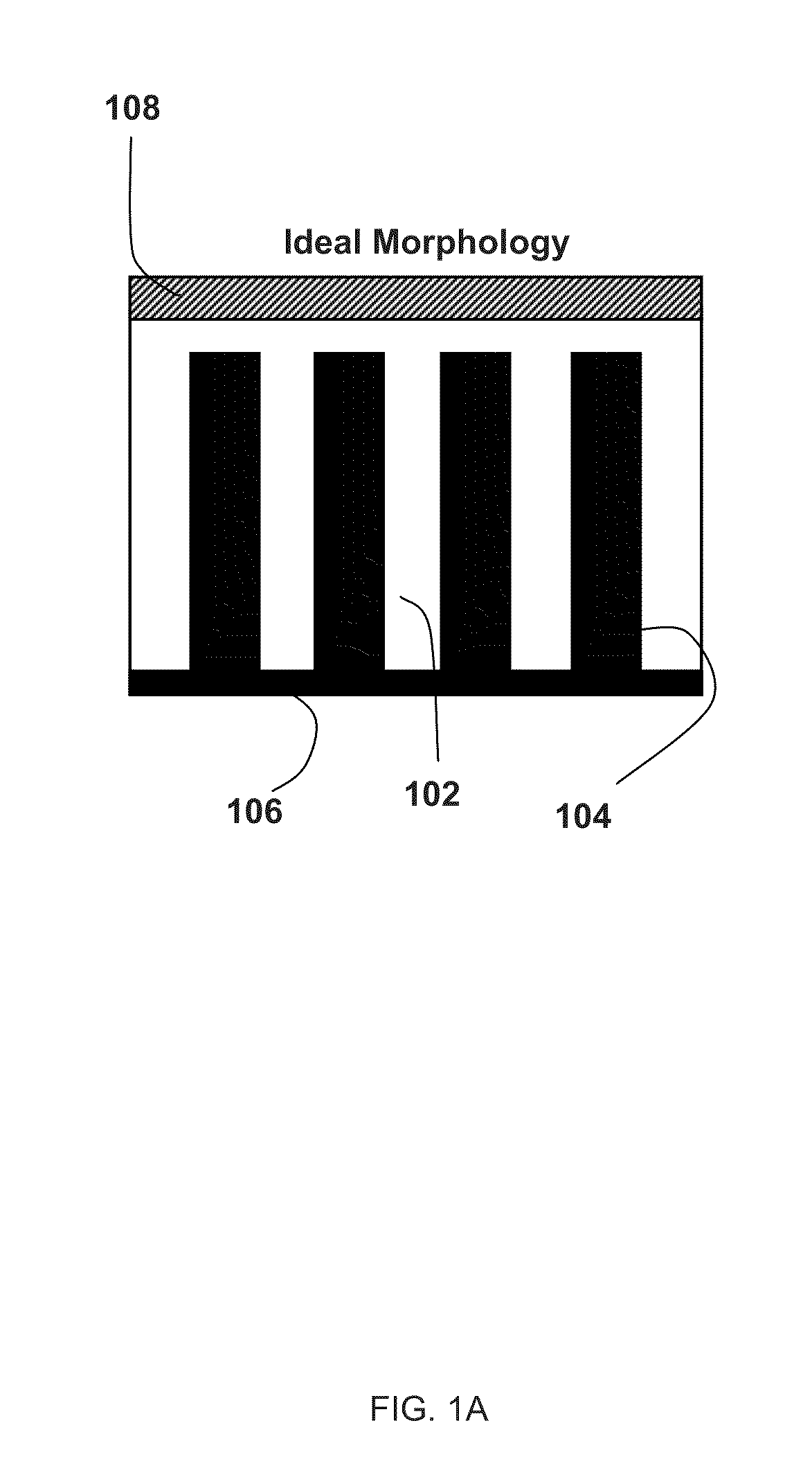
[0012]The present invention provides methods of using magnetic or electric fields to align semiconductor nanoparticles as they are blended with photovoltaic materials to form devices, as well as devices made from such methods. In order to do this, nanoparticles are magnetically doped, i.e., attached to one or more atoms of a magnetic material The dopant may be ferromagnetic or paramagnetic. The nanoparticles are added in sufficient quantity to form a conductive channel to an electrode. The quantity of nanoparticles may be advantageously reduced in the present device, because the particles can be properly arranged and need not occupy space otherwise available to photovoltaic polymer. This is advantageous when using particles such as fullerenes, which do not absorb light. Thus one may use a ratio of about 1:1 nanoparticles to polymer, or less, such as 1:2. The alignment of the nanoparticles essentially also results in an alignment of the polymer between the particles.
[0015]In another aspect of the invention, a particular magnetic field or electric field is used to direct an alignment of the magnetically functionalized semiconductor nanoparticles, so as to direct them into an improved configuration for accepting a member of an exciton pair in a polymeric photovoltaic cell. The cell is formed as a thin film on a substrate, and an electromagnetic field emitting apparatus is positioned adjacent to the substrate while the polymer is in a fluid state, so as to cause the magnetically functionalized nanoparticles within the polymer to move into a desired configuration.

Problems solved by technology

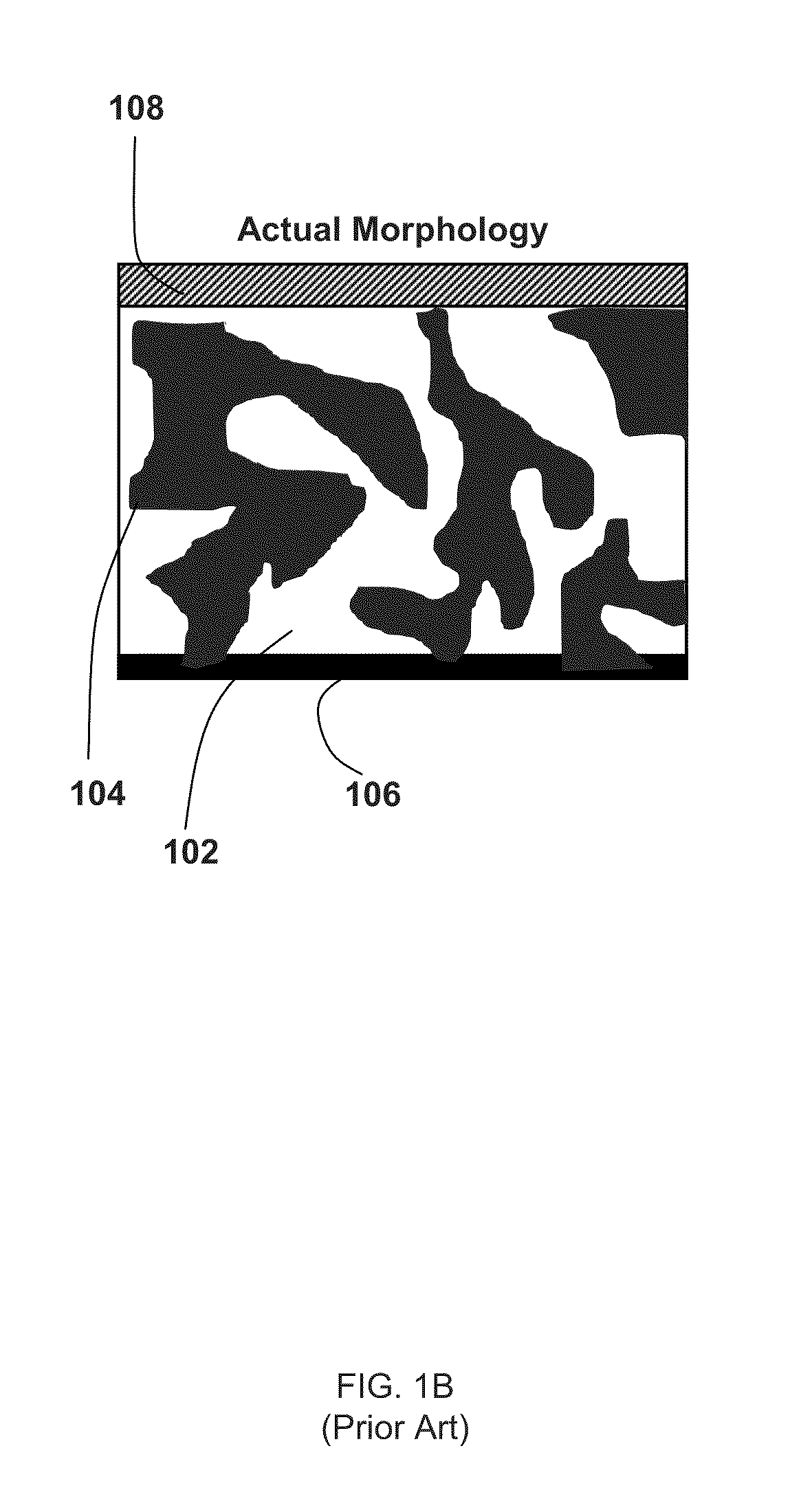
However, to date the best efficiencies achieved with these solar cells is 5-6%, still far too low for many practical applications.

Method used


Image

  • Controlled Alignment in Polymeric Solar Cells
  • Controlled Alignment in Polymeric Solar Cells
  • Controlled Alignment in Polymeric Solar Cells

Examples


Embodiment Construction

Definitions

[0026]Unless defined otherwise, all technical and scientific terms used herein have the same meaning as commonly understood by those of ordinary skill in the art to which this invention belongs. Although any methods and materials similar or equivalent to those described herein can be used in the practice or testing of the present invention, the preferred methods and materials are described. Generally, nomenclatures utilized in connection with, and techniques of, material science, physics and chemistry are those well known and commonly used in the art. Certain experimental techniques, not specifically defined, are generally performed according to conventional methods well known in the art and as described in various general and more specific references that are cited and discussed throughout the present specification.

[0027]The term “photovoltaic device” is used in its conventional sense to mean a solid-state electrical device that converts light directly into direct curren...


PUM

PropertyMeasurementUnit
thickaaaaaaaaaa
diameteraaaaaaaaaa
diameteraaaaaaaaaa

Abstract

Disclosed are methods of using magnetic or electric fields to align magnetically responsive nanoparticles in a polymeric matrix, which has not yet been completely solidified. The nanoparticles are preferably magnetically doped, then blended with photovoltaic polymer material to form devices. The methods provided are particularly useful for the formation of solar cell devices. The devices include nanostructured electron-conducting channels arranged approximately parallel to one another, where the channels comprise magnetically doped materials, as well as photovoltaic materials interspersed with the nanostructured electron-conducting channels. The method provides a way to control the morphology of blended photovoltaic devices, which will improve efficiencies. In addition, the new method provides a way to control the growth of novel, cheap, solar cells, which can in turn lead to enhanced performance.

Description

RELATED APPLICATIONS[0001]This application is the national phase application of International application number PCT / US2009 / 058549, filed Sep. 28, 2009, which claims priority to and the benefit of U.S. Provisional Application No. 61 / 101,233, filed on Sep. 30, 2008, which is hereby incorporated by reference in its entirety.STATEMENT OF GOVERNMENTAL SUPPORT[0002]This invention was made with government support under Contract No. DE-AC02-05CH11231 awarded by the U.S. Department of Energy and under National Science Foundation COINS Grant No EEC-0425914. The government has certain rights in the invention.FIELD OF THE INVENTION[0003]The present invention relates to the field of materials science, and more particularly to the fabrication of polymeric solar cells.BACKGROUND OF THE INVENTION[0004]Polymer based photovoltaic devices are an attractive alternative to conventional, inorganic solar cells. These lightweight elements for solar energy conversion have various important advantages over ...

Claims


Application Information

Patent Timeline
Patent Type & Authority Applications(United States)
IPC IPC(8): H01L51/46H01L31/0248H01L31/06B82Y99/00
CPCB82Y10/00H01L51/0012H01L51/0036Y02E10/549H01L51/0047H01L51/4253H01L51/0037Y02P70/50H10K71/191H10K85/1135H10K85/215H10K85/113H10K30/30H10K30/50
Inventor GROSSMAN, JEFFREY C.ZETTL, ALEXANDER K.
Owner RGT UNIV OF CALIFORNIA
Learn More