
Expansion Seal, Especially for Gases

a technology of expansion seals and sealing elements, applied in the field of expansion seals, can solve the problems of reducing the sealing properties of metal seals, no longer being sealed, and reducing the sealing properties of o-rings with respect to helium, so as to increase the sealing material's effectiveness, and reduce the demands of the surface smoothness of the sealing elements. surprisingly the effect of pressur

Active Publication Date: 2011-10-20
SCHWER FITTINGS
View PDF23 Cites 21 Cited by
  • Summary
  • Abstract
  • Description
  • Claims
  • Application Information

AI Technical Summary

Benefits of technology

[0027]It has been found that by means of a particular design of sealing ring and flanges an even better, almost absolute tightness can be achieved. Surprisingly, it has also been found that steel, an actually outermost elastic material, assumes plastic properties under extremely great pressure, which due to the pressure-related material flow allow to provide steel fittings with seals likewise made of steel.

Problems solved by technology

For this purpose, however, the surfaces to be sealed should have a smooth surface not achievable in practice, or the force which urges the surfaces to be sealed against each other would have to be so great that all cavities still present between the sealing surfaces are leveled out by material flow to such an extent that the molecules of the medium to be sealed no longer can pass through the resulting boundary zones between the sealing surfaces, because their distance from each other generally is smaller than the effective molecule diameter of the gas.
Experiments have shown that at such a high pressure, the boundary surfaces are deformed non-uniformly, so that they can no longer be sealed after demounting the flanges.
Understandably, the sealing of connections of pipes with flanges under high pressure or high vacuum creates particular difficulties when the medium to be sealed is hydrogen or helium, since both elements have the smallest possible molecule diameter of all volatile substances and thus also can escape through smallest leaks in the case of pressure differences.
However, the sealing properties of said O-rings with respect to e.g., helium are worse than those of metal seals at least by a factor of 10−6.
A disadvantage of this configuration is the difficult separation of such compounds, for instance during maintenance work (cf. p.
A particular shape of the seals is not important here, but the application thereof is very complicated.
However, as compared to the current scientific and technical requirements, this is no longer sufficient.
Hence it can be concluded that materials exhibiting an elastic behavior under the pressing conditions are less suitable.
This ensures that the seal itself is completely kept free of forces acting from outside, which can greatly deteriorate the sealing quality.

Method used


Image

  • Expansion Seal, Especially for Gases
  • Expansion Seal, Especially for Gases
  • Expansion Seal, Especially for Gases

Examples


Embodiment Construction

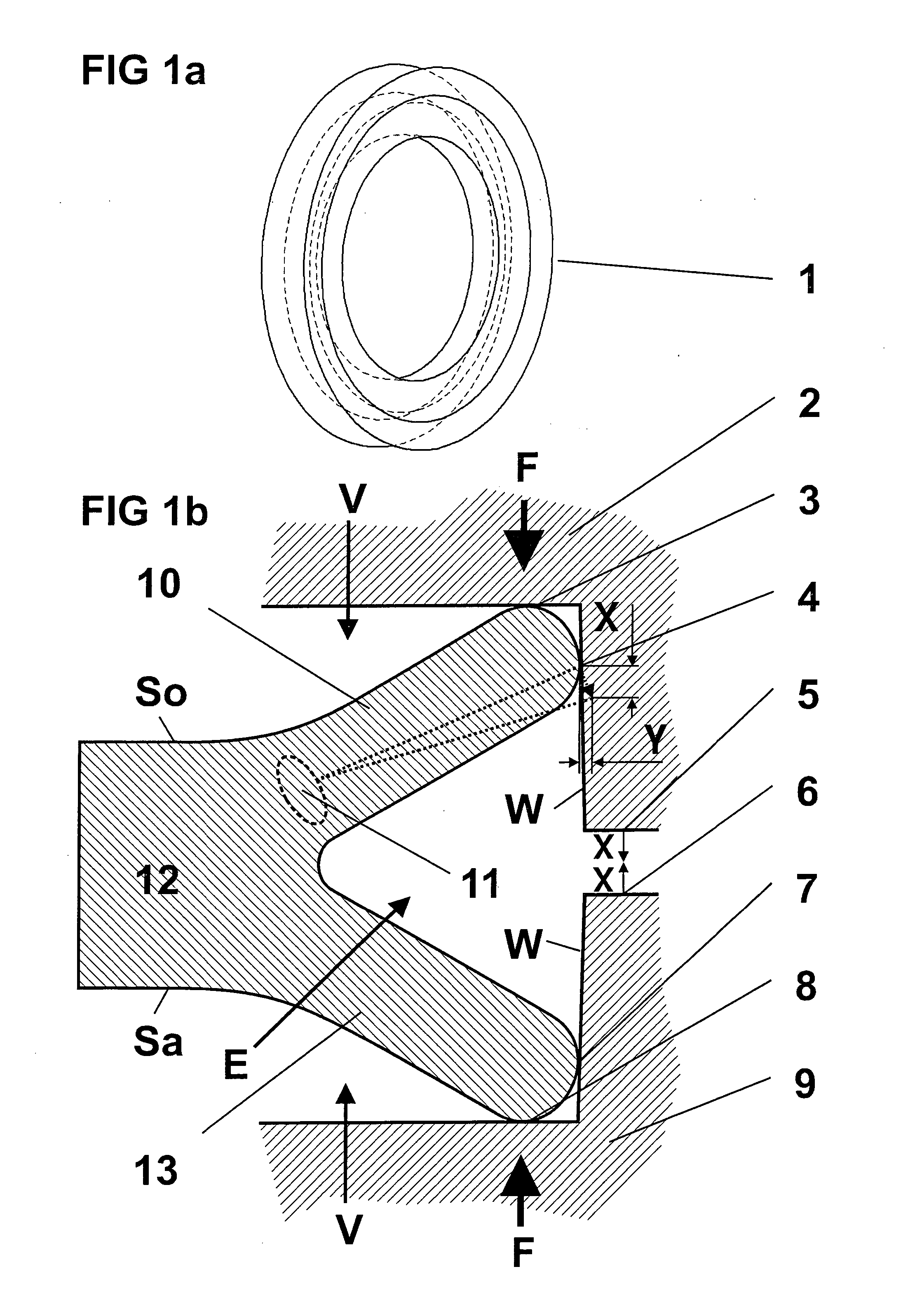
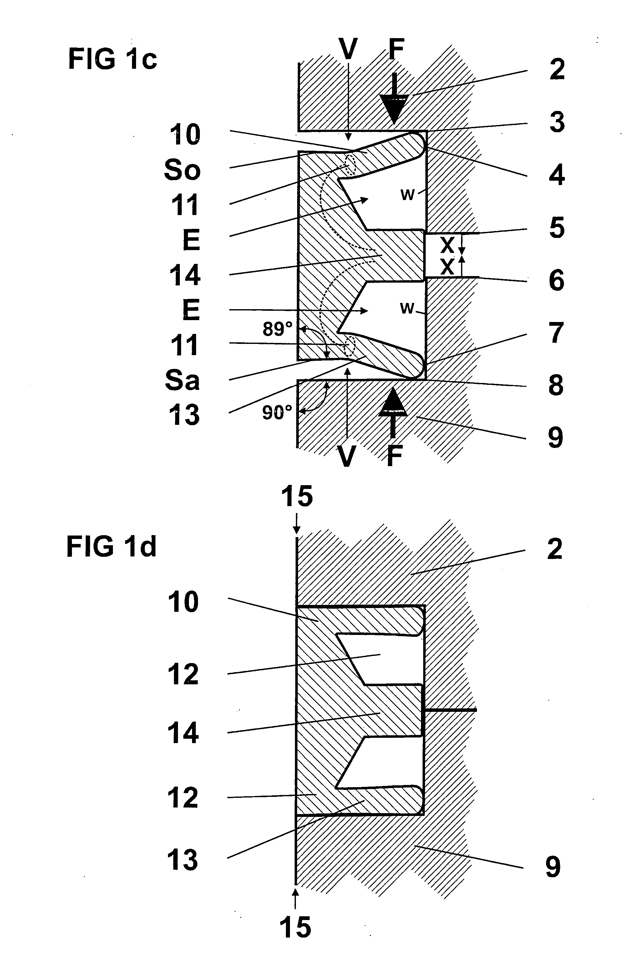
[0036]A sealing ring as schematically shown in FIG. 1 is shaped like a wheel rim. A Y-shaped indentation (E) is shown in section in particular in FIGS. 1b-1d.

[0037]What turned out to be particularly favorable according to FIG. 1a is an arrangement of the legs (10+13) protruding beyond the thickness of the seal in the inner zone, in which before the pressing operation the axes of the legs form an angle of about 45° with the inner wall (W) of the flange. This arrangement is particularly preferred, because the forces produced during the pressing operation thereby are uniformly distributed over the two legs and thus form two sealing zones perpendicular to each other, which together achieve a particularly good tightness. In this case, the two disks corresponding to the legs of FIG. 1b are positioned at an angle of 90° with respect to each other before pressing.

[0038]A non-rotatable flange connection for better handling is achieved in that before the pressing operation the clearance desi...


PUM

PropertyMeasurementUnit
Diffusion barrieraaaaaaaaaa
Pressureaaaaaaaaaa
Shapeaaaaaaaaaa

Abstract

A flange connection for connecting e.g. two sections of a tube or pipe comprises two flanges and a sealing ring inserted into an annular sealing space defined by radial faces and axially extending peripheral walls between the flanges. The sealing ring has an annular main body and an outer periphery with a cross-sectional shape that has legs extending outwardly from the main body. These legs, in a condition prior to application of sealing pressure, are inclined away from each other and have rounded outer ends that abut both the radial faces and the peripheral walls defining the annular sealing space. The legs, in a condition where the flanges are forced against each other, are axially compressed and upset at least in a radial direction by plastic flow of material on the outer ends in sealing engagement with the axially extending peripheral walls. Preferably, the sealing ring is formed with an annular shoulder that extends radially outwardly from an outer peripheral area of the main body and that is centrally located between the legs.

Description

FIELD OF THE INVENTION[0001]The invention relates to an expansion seal and to a flange connection using n expansion seal.BACKGROUND OF THE INVENTION[0002]The EP application 07 019 555.7 describes a sealing device for pipes, which contains correspondingly flexible soft metals or soft metal alloys such as tin, lead, indium, gold, copper, aluminum, in particular metal alloys with a Mohs hardness between 1 and 3 as sealing compound, and methods for the manufacture and use thereof, which can be used in pipes or bodies to be sealed of similar type and construction, in particular instead of seals of elastomeric and / or polymeric materials.[0003]In particular, said application relates to a novel and highly effective arrangement of the sealing elements which provide for a substantial improvement of the tightness of sealing systems in particular with respect to volatile media such as hydrogen and helium.[0004]The advantage of such seal consists in a substantial reduction of the diffusion of ex...

Claims


Application Information

Patent Timeline
IPC IPC(8): B65D39/00F16J15/08F16L23/20F16L23/16F16L23/18
CPCB65D39/025B65D39/12B65D41/62F16L55/132F16L23/20F16L55/115F16L19/0218
Inventor HISS, LUDWIG
Owner SCHWER FITTINGS
Learn More