
Coherent transceiver and related method of operation

a transceiver and coherent technology, applied in the field of high accuracy, can solve the problems of difficult to achieve theoretical resolving power in practice, affecting the operation of systems using stepped frequency waveforms, and affecting the operation of the transceiver, etc., to achieve high controllability, simple switch and mixer network, and fast settling time

Inactive Publication Date: 2011-10-20
APPLIED SIGNALS INTELLIGENCE
View PDF3 Cites 5 Cited by
  • Summary
  • Abstract
  • Description
  • Claims
  • Application Information

AI Technical Summary

Benefits of technology

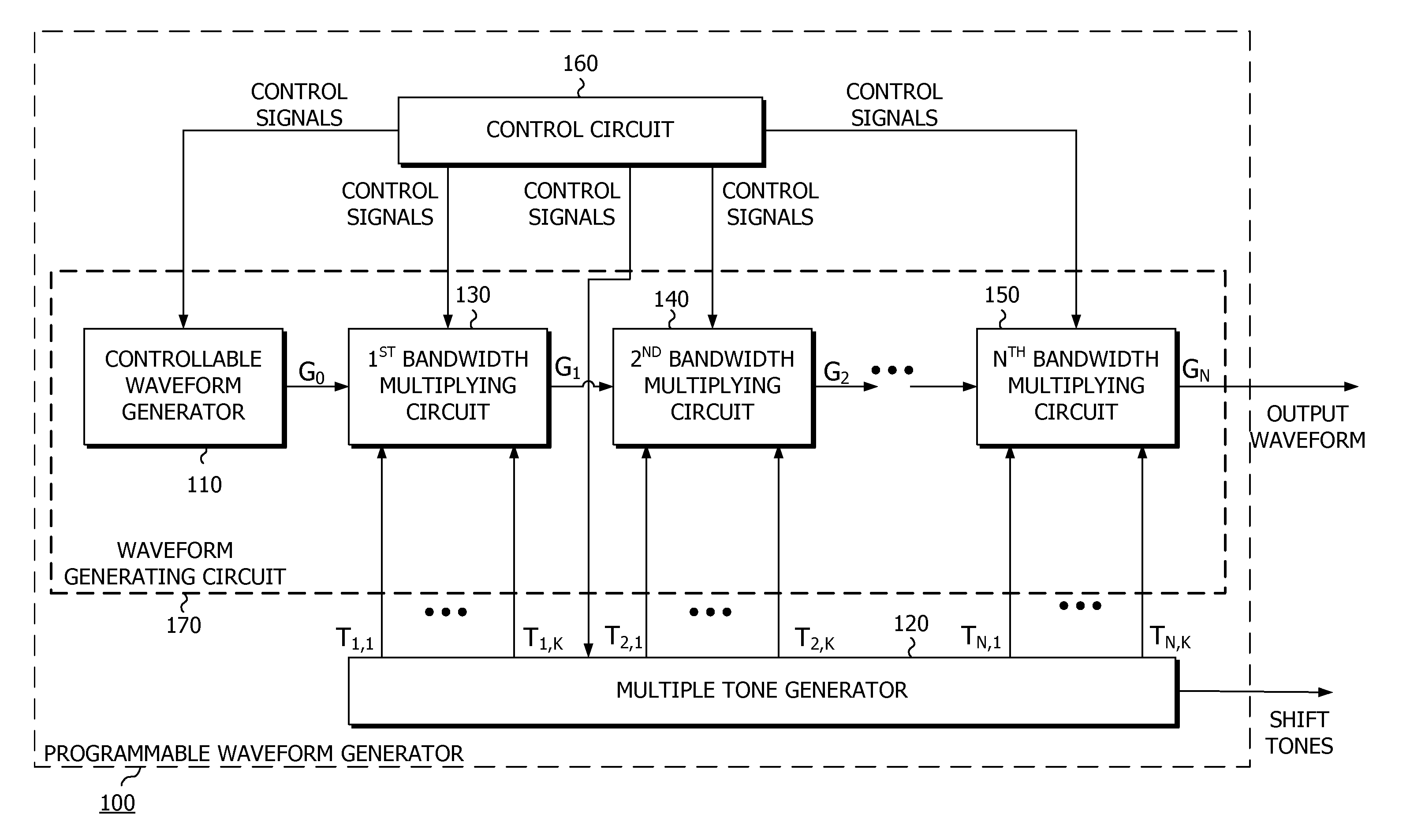
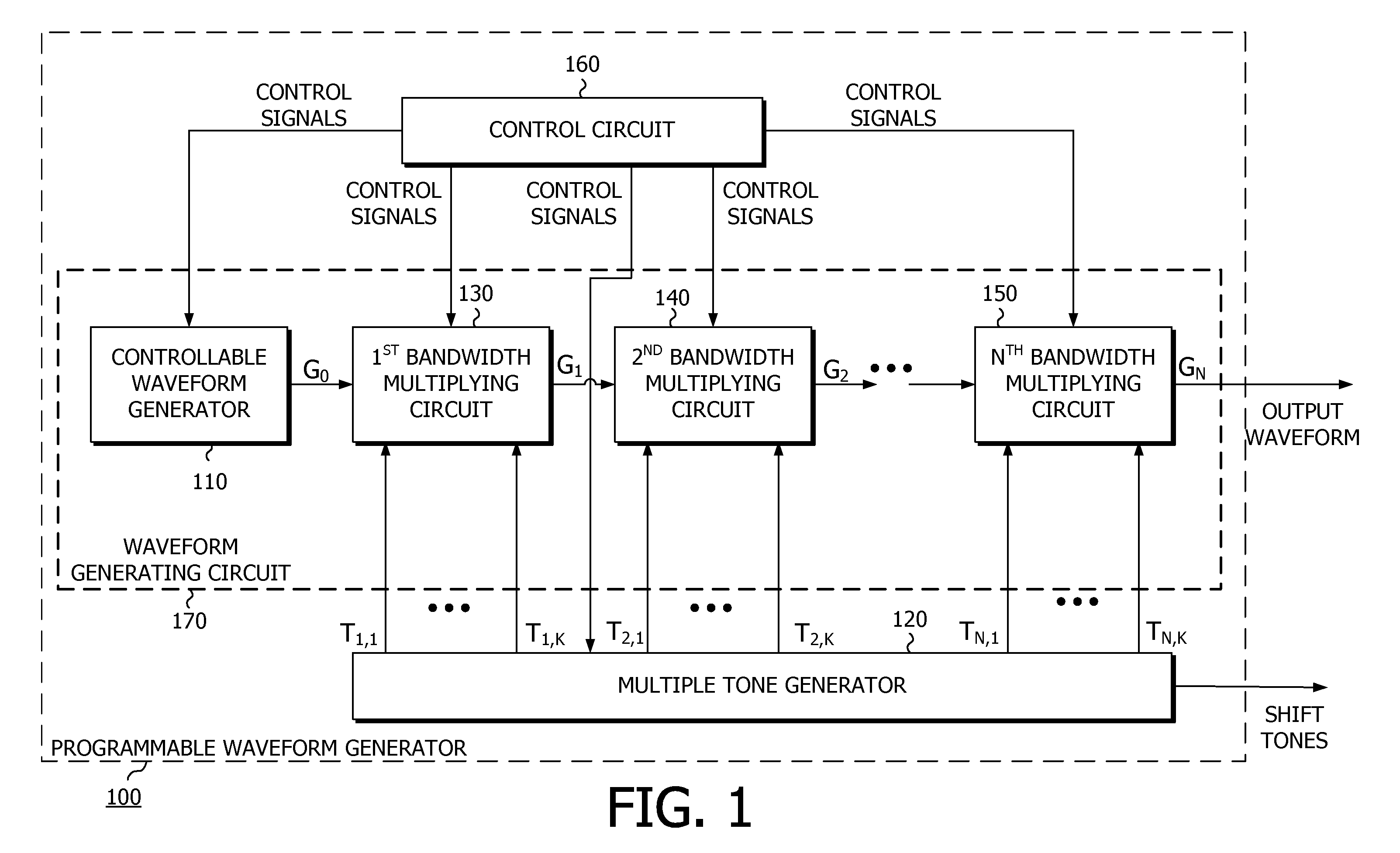
"The patent describes a method for generating an extended bandwidth output signal using a programmable waveform generator and a multiple tone generator. This allows for high controllability and low phase noise in the initial signal. The extended bandwidth output signal is then used to create the signal for transmission and the initial bandwidth signal is also used to create the local oscillator signals for mixing with the received signal. The method reduces the number of parts and power required. The extended bandwidth output signal can be used to create a radar transceiver. The technical effects of the patent are improved bandwidth and reduced phase noise in the initial signal, improved controllability, and reduced power and space requirements."

Problems solved by technology

The difficulty of making a filter both tunable and extremely sharp, and extremely stable, has caused nearly all radios to use a super-heterodyne process because the hard-to-implement tunable filter is replaced with a simple highly optimized fixed tuned filter.
As a result, the burden of tuneability and stability fall on the variable frequency signal generator.
As the time bandwidth product grows, however, achieving the theoretical resolving power in practice becomes difficult due to the extremely high linearity required on the frequency ramp.
Systems that use stepped frequency waveforms are hindered by the settling time that must occur at each frequency step.
The net result is that there is a duty cycle reduction caused by the required settling time, and typically some performance degradation because in order to increase the duty cycle and save time, the system is allowed to run before a step is fully settled.
Typically, the wider spans and random nature of the hopping causes the settling times to be worse than sequentially stepped systems, ultimately causing an even worse duty cycle.
Each method results in different sets of advantages and disadvantages in terms of metrics such as size, cost, weight, power consumption, settling time after a frequency change, modulation bandwidth, modulation linearity, long and short term stability, harmonic levels, spurious levels, and flexibility or ease of control.
Numerically controlled oscillators are well known to achieve optimally fast (short) settling times. At the same time, due to a combination of their discrete-time digitally-sampled stair-step output waveform, and the fact that the stair-step output levels must settle in each time-step period, an NCO cannot be clocked fast enough to produce the bandwidth required by many applications.
Many applications are extremely sensitive to spurious signals.
Applications such as radar, ladar (LAser Detection And Ranging), sonar, and numerous instrumentation applications, are fundamentally limited by the SFDR of the signals they generate and use to perform their function.
Harmonic and spurious signals correlate along with the desired signal, causing an error in the measured correlation, which is supposed to only come from the desired signal.
This method results in a high noise floor and is unsuitable for many applications.
Additionally, if the initial waveform was a complex waveform with, for example, a desired spectral notch, the multiplication process would destroy the notch.
This method results in a high power and a physically large and costly system that is incompatible with many applications.
The relatively slow switching speed of the PLL's in this solution, however, makes it unsuitable for many applications.

Method used


Image

  • Coherent transceiver and related method of operation
  • Coherent transceiver and related method of operation
  • Coherent transceiver and related method of operation

Examples


Embodiment Construction

[0063]The instant disclosure is provided to further explain in an enabling fashion the best modes of performing one or more embodiments of the present invention. The disclosure is further offered to enhance an understanding and appreciation for the inventive principles and advantages thereof, rather than to limit in any manner the invention. The invention is defined solely by the appended claims including any amendments made during the pendency of this application and all equivalents of those claims as issued.

[0064]It is further understood that the use of relational terms such as first and second, and the like, if any, are used solely to distinguish one from another entity, item, or action without necessarily requiring or implying any actual such relationship or order between such entities, items or actions. It is noted that some embodiments may include a plurality of processes or steps, which can be performed in any order, unless expressly and necessarily limited to a particular or...


PUM


Abstract

A transceiver is provided, comprising: a programmable waveform generator configured to generate a base signal, the programmable waveform generator including a controllable waveform generator configured to generate an initial bandwidth signal having an initial frequency bandwidth; a multiple tone generator configured to generate a plurality of tone signals, each tone signal having a different frequency; one or more bandwidth multiplying circuits; and a control circuit a controller configured to control the operation of the controllable waveform generator, the tone generator and the one or more bandwidth multiplying circuits; a transmit port configured to output the base signal; a receive port configured to accept a received signal; a 90-degree splitter configured to receive the base signal and to generate a first split signal at a 0-degree output and a second split signal at a 90-degree output, the first and second split signals being separated by 90 degrees in phase; a first-mixer configured to mix the received signal and the first split signal to generate a quadrature-phase signal; and a second-mixer configured to mix the received signal and the second split signal to generate an in-phase signal.

Description

CROSS-REFERENCE TO RELATED PATENT DOCUMENTS[0001]This application relies for priority on U.S. provisional application Ser. No. 61 / 323,875, by John W. McCorkle, filed 14 Apr. 2010, entitled “COHERENT TRANSCEIVER AND RELATED METHOD OF OPERATION,” the contents of which is hereby incorporated by reference in its entirety.FIELD OF THE INVENTION[0002]This application relates to high accuracy, low noise, small footprint, wide bandwidth, radar (RAdio Detection And Ranging), communications, and test instrumentation such as spectrum analyzers and network analyzers. All of these applications benefit from the ability to sweep or switch, across wide bandwidths, to a new frequency. The performance of these systems is tied to the speed of settling to a new frequency in a state of low drift, and low phase-noise. These applications also benefit from the ability to sweep across a wide frequency range with extreme linearity. This application relates to extending the performance of these systems in a s...

Claims


Application Information

Patent Timeline
Patent Type & Authority Applications(United States)
IPC IPC(8): H04B1/44
CPCH04B1/408
Inventor MCCORKLE, JOHN W.
Owner APPLIED SIGNALS INTELLIGENCE
Learn More