Base station device, mobile station device, communication system, and communication method

Active Publication Date: 2011-10-20
SHARP KK
View PDF1 Cites 51 Cited by
  • Summary
  • Abstract
  • Description
  • Claims
  • Application Information

AI Technical Summary

Benefits of technology

[0046]A base station device, a mobile station device, a communication system, and a communication method of

Problems solved by technology

One problem in executing the aggregation is the degradation of carrier metrics by a downlink reference signal.
Another problem in ex

Method used


Image

  • Base station device, mobile station device, communication system, and communication method
  • Base station device, mobile station device, communication system, and communication method
  • Base station device, mobile station device, communication system, and communication method

Examples


first embodiment

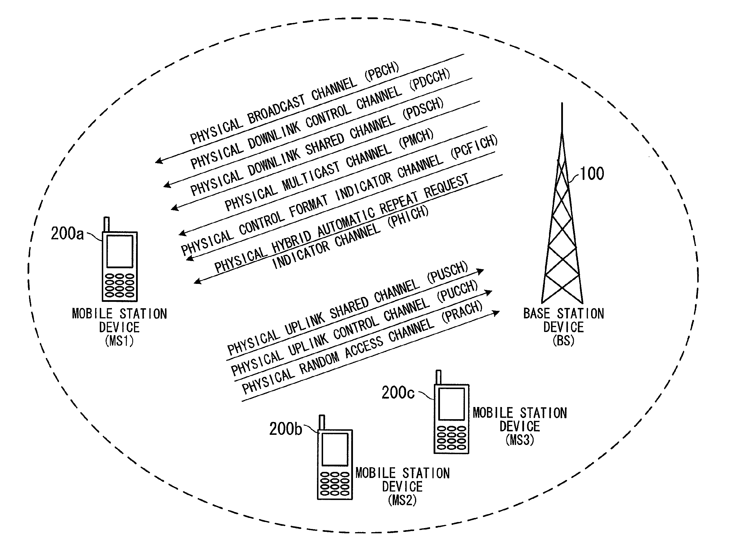
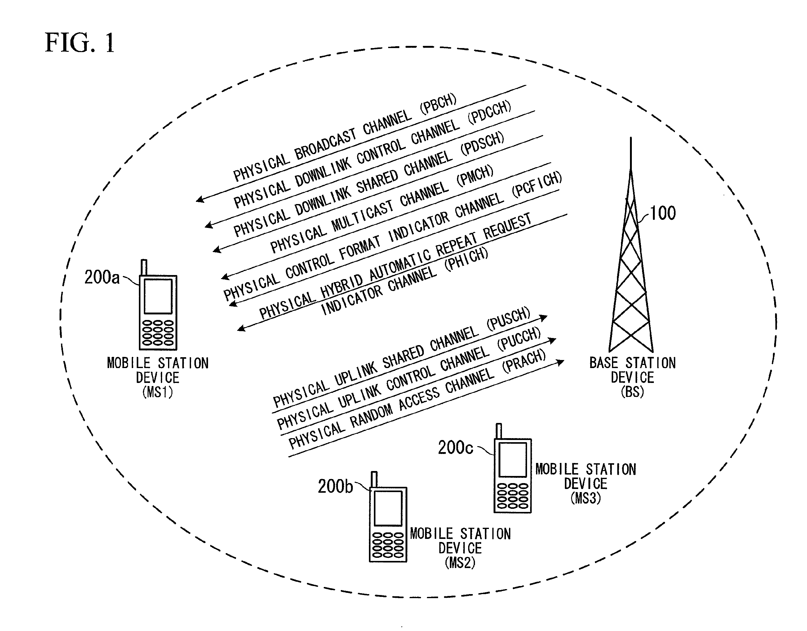
[0068]The first embodiment of the present invention will be described. A wireless communication system according to the embodiment includes one or more base station devices and one or more mobile station devices between which wireless communication is performed. FIG. 1 is a diagram showing the communication system according to the embodiment. The case where an aggregation is performed in the communication system shown in FIG. 1 will be described.

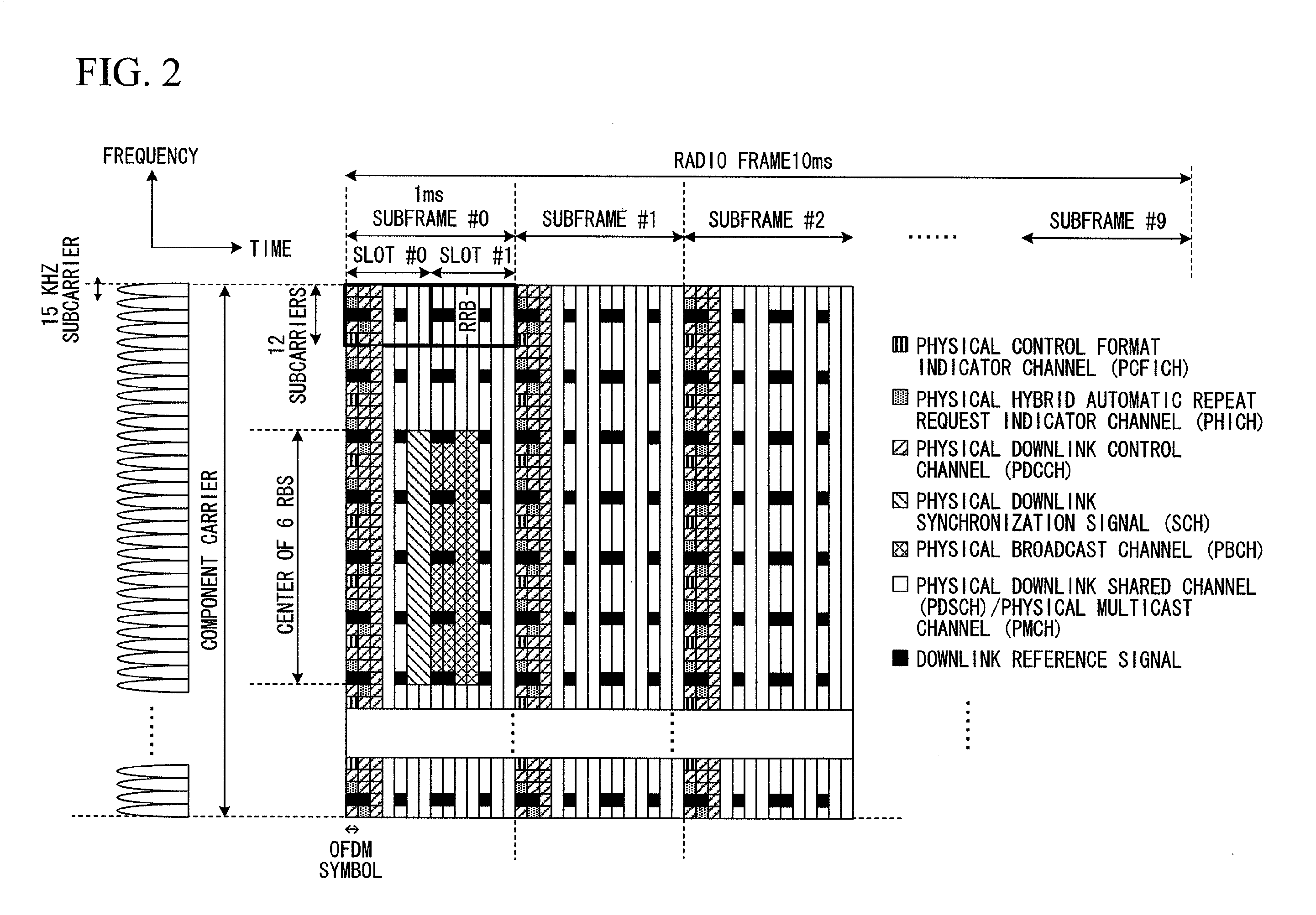
[0069]First, physical channels of one CC identical to those of FIGS. 2 and 3 may be used. FIG. 2 shows physical channels of a downlink. A PBCH is mapped to broadcast information at an interval of 40 ms. The timing of 40 ms is subjected to blind detection or blind decoding. That is, explicit signaling for timing presentation may not be performed. The PBCH can be decoded in its subframe, that is, is self-decodable.

[0070]A PDCCH is a channel that is used to notify a mobile station device of PDSCH resource allocation, hybrid ARQ (HARQ) informati...

second embodiment

[0182]The second embodiment of the present invention will be described. A base station device and a mobile station device according to the embodiment may be implemented by substantially the same block configurations as those of the base station device 100 and the mobile station device 200 shown in FIGS. 5, 6, 7, and 8 described in the first embodiment. Hereinafter, differences from the first embodiment of FIGS. 5, 6, 7, and 8 according to a sequence of PCI setting of each CC related to the embodiment will be described.

[0183]FIG. 11 is a sequence diagram showing processing of the wireless communication system according to the embodiment. First, the base station device 100 transmits a downlink synchronization signal corresponding to a PCI in a synchronization CC (step S1101).

[0184]The mobile station device 200 acquires the downlink synchronization signal transmitted from the base station device 100 by cell selection or cell re-selection processing, and acquires the PCI of the synchron...

third embodiment

[0197]The third embodiment of the present invention will be described. In the embodiment, description focusing on a downlink reference signal of each CC is given. A base station device and a mobile station device according to the embodiment may be implemented by substantially the same block configurations as those of the base station device 100 and the mobile station device 200 shown in FIGS. 5, 6, 7, and 8 described in the first embodiment or the second embodiment.

[0198]FIG. 13 is a diagram showing an example of a physical downlink frame format according to the embodiment. CC #2 is a synchronization CC and a physical downlink synchronization signal is inserted into a predetermined band of CC #2. CC #1 and CC #3 are extended CCs. Normally, no physical downlink synchronization signal is inserted into a band into which the physical downlink synchronization signal is inserted.

[0199]A stream to be used in a downlink reference signal of CC #2 is generated according to a predetermined gen...


PUM


Abstract

A communication system which performs communication between a base station device configuring at least one cell and a mobile station device, wherein: the base station device includes: a synchronization signal generation unit which generates a synchronization signal corresponding to a cell identity for identifying a cell; and a transmission unit which generates a first transmission signal including the synchronization signal using a first parameter obtained from the cell identity, generates a second transmission signal excluding the synchronization signal using a second parameter obtained from a virtual cell identity different from the cell identity, transmits the first transmission signal using a first frequency band, and transmits the second transmission signal via a second frequency band different from the first frequency band. The mobile station device includes: a reception unit which receives a first reception signal including the synchronization signal using the first parameter obtained from the cell identity via the first frequency band and receives a second reception signal using the second parameter obtained from the virtual cell identity via the second frequency band.

Description

TECHNICAL FIELD[0001]The present invention relates to a base station device, a mobile station device, a communication system, and a communication method.[0002]This application claims priority to and the benefits of Japanese Patent Application No. 2008-331652 filed on Dec. 26, 2008, the disclosure of which is incorporated herein by reference.BACKGROUND ART[0003]3GPP (Third Generation Partnership Project) is a project in which specifications of mobile phone systems based on an evolved network of W-CDMA (wideband code division multiple access) and a GSM (global system for mobile communications) are studied and created.[0004]In 3GPP, a W-CDMA scheme has been standardized as a 3rd generation cellular mobile communication scheme and its services have been sequentially initiated. Also, HSDPA (high-speed downlink packet access) having a higher communication rate has been standardized and its services have been initiated.[0005]In 3GPP, EUTRA (evolved universal terrestrial radio access), whic...

Claims


Application Information

Patent Timeline
IPC IPC(8): H04W60/00H04W4/00
CPCH04J11/0069H04W56/00H04W48/16H04L5/0048H04W76/10H04L5/0055H04W48/08H04W88/02H04W88/08H04L5/001
Inventor NOGAMI, TOSHIZOAIBA, TATSUSHIYAMADA, SHOHEITSUBOI, HIDEKAZUUEMURA, KATSUNARINAKASHIMA, DAIICHIROSUZUKI, SHOICHI
Owner SHARP KK
Why Eureka
Try Eureka