Control device for vessel equipped with exhaust heat recovery system and the vessel equipped with the control device

Inactive Publication Date: 2011-10-20
MITSUBISHI HEAVY IND LTD
View PDF4 Cites 4 Cited by
  • Summary
  • Abstract
  • Description
  • Claims
  • Application Information

AI Technical Summary

Benefits of technology

[0018]In view of the problems above, an object of the present invention is to provide a control device for a vessel equipped with an exhaust heat recovery system and the vessel equipped with the control device which can suppress change of the vessel speed due to the rapid drop in the load within the vessel with improved responsiveness.
[0020]According to the invention, the standard fuel injection amount is corrected by subtracting the first correction value obtained from the feedfoward controller 25, 26 from the standard fuel injection amount obtained from the feedback controller 24 so that the fuel injection amount can be corrected in response to the surplus power due to the rapid drop in the load within the vessel. As a result, the fuel injection amount can be controlled to meet the target rotation speed when the load within the vessel decreases rapidly, and thus the change of the vessel speed can be controlled with better responsiveness.
[0022]By this, the fuel injection amount of the internal combustion engine can be adjusted and the change of the vessel speed can be controlled so as to achieve the target rotation speed of the propeller even when the load within the vessel decreases. As a result, the system itself can be simplified as well.
[0026]By this, the vessel having the control device equipped with the exhaust heat recovery system can suppress the change of the vessel speed with better responsiveness when the load within the vessel decreases rapidly.
[0028]According to the present invention, it is possible to provide the control device for the vessel equipped with the exhaust heat recovery system and the vessel equipped with the control device that can suppress change of the vessel speed due to the rapid drop in the load within the vessel with improved responsiveness.

Problems solved by technology

However, the device of Patent Document 2 improves the turning responsiveness of the vessel and does not enhance the propelling responsiveness of the vessel or control the condition of the engine in response to the rotation speed of the propeller.
Therefore, when the rapid drop in the load within the vessel generates surplus electricity, there is torque turbulence of the assist torque from the shaft and thus the vessel is rapidly accelerated.

Method used


Image

  • Control device for vessel equipped with exhaust heat recovery system and the vessel equipped with the control device
  • Control device for vessel equipped with exhaust heat recovery system and the vessel equipped with the control device
  • Control device for vessel equipped with exhaust heat recovery system and the vessel equipped with the control device

Examples


second preferred embodiment

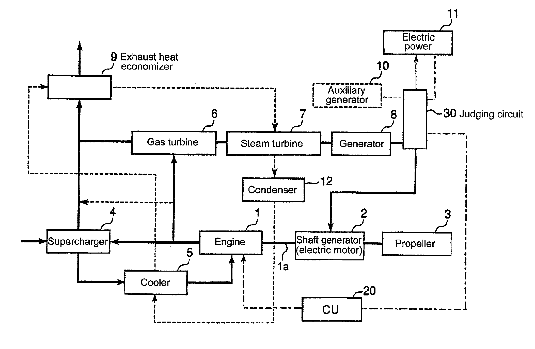
[0058]Now, a fuel injection amount control in relation to a second preferred embodiment is explained in reference to FIG. 5. The general structure of the exhaust heat recovery system of the second preferred embodiment is similar to that of FIG. 1 and thus the structure thereof is not explained further. Further, in the second preferred embodiment, an electronically-controlled engine which controls the fuel injection electronically by an electronic governor or the like is used as the internal combustion engine 1.

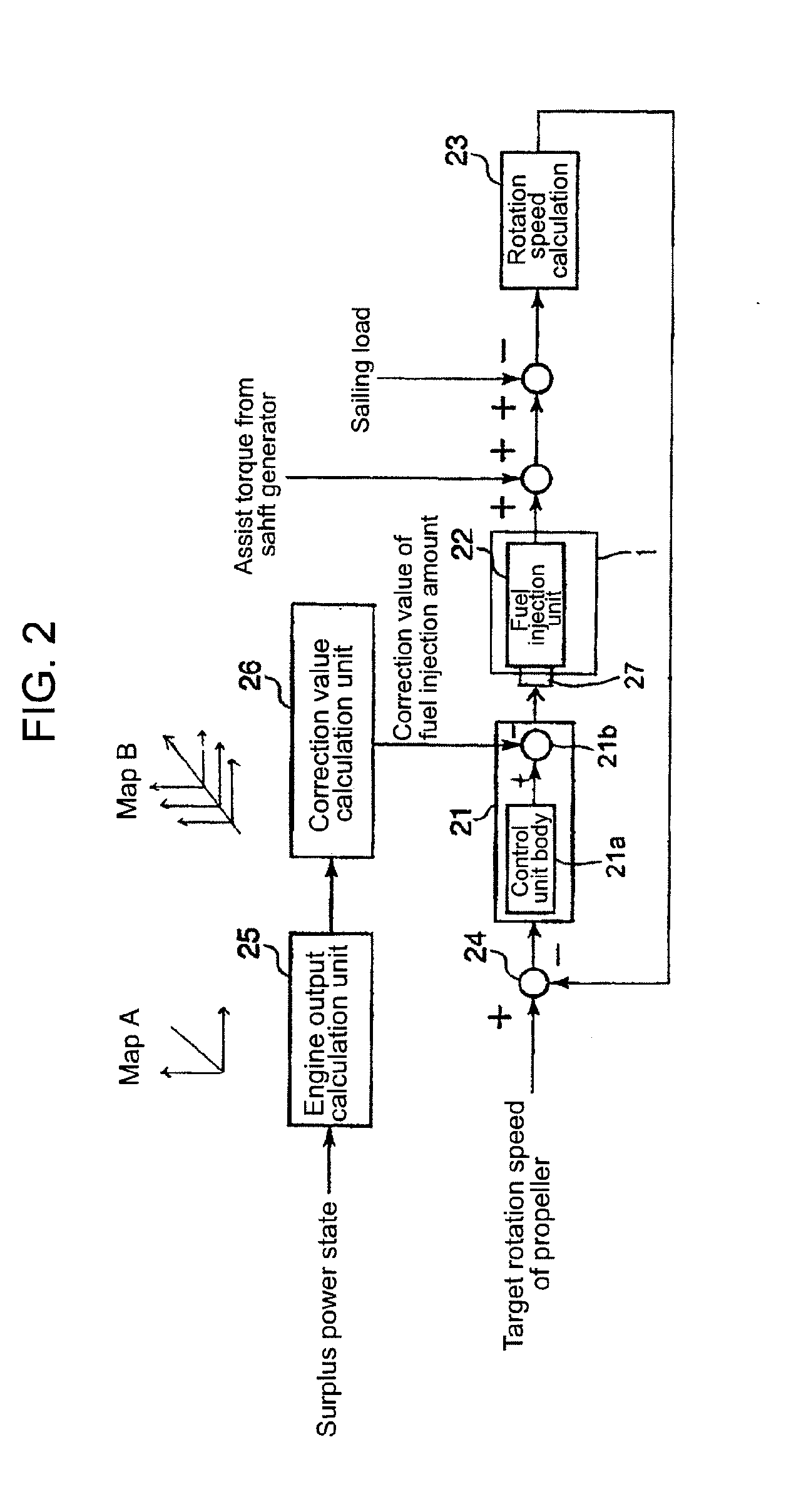
[0059]FIG. 5 is a block diagram illustrating components of the fuel injection amount control logic for the vessel in relation to the second preferred embodiment. While the mechanical actuators are used as the control units for controlling the fuel injection in FIG. 2, the electronically-controlled engine is used to control the fuel injection electronically by the electronic governor or the like in FIG. 5.

[0060]In FIG. 5, the target rotation speed of the propeller is obtained f...

third preferred embodiment

[0066]Now, a fuel injection amount control in relation to a third preferred embodiment is explained in reference to FIG. 6. The general structure of the exhaust heat recovery system of the second preferred embodiment is similar to that of FIG. 1 and thus the structure thereof is not explained further. Further, in the third preferred embodiment, an electronically-controlled engine, which controls the fuel injection electronically, is used as the internal combustion engine 1 in the same manner as the second preferred embodiment.

[0067]In the third preferred embodiment, the vessel speed is directly controlled to the target speed requested by the vessel operator. The control logic thereof is illustrated in FIG. 6.

[0068]Different from FIG. 5, FIG. 6 shows a GPS 42 for locating the vessel, a vessel speed calculation unit 43 for calculating an actual output of the vessel speed from data from the GPS, a vessel speed setting unit 44 for setting the target vessel speed based on the request fro...


PUM


Abstract

A ship powered by an internal combustion engine (1) and an electric motor (2) connected to a propeller (3) powered by surplus electric power obtained by a thermal discharge recovery system has a controller including a feedback control section for controlling a base amount of fuel injected to the internal combustion engine (1) based on the difference between the target number of rotation of the propeller given by the operator and the real number of rotation, and a feed-forward control section having a means (25) for calculating an overall power output and a means (26) for calculating a correction in the amount of fuel injected to the internal combustion engine based on the overall power output and the number of rotation of the propeller. The base amount of fuel is corrected by subtracting the correction obtained by the feed-forward section from the base amount of fuel calculated by the feedback control section whereby preventing a rapid change in the speed of the ship due to rapid change in ship loads.

Description

BACKGROUND OF THE INVENTION[0001]1. Field of the Invention[0002]The present invention relates a control device for a vessel equipped with an exhaust heat recovery system and the vessel equipped with the control device. The exhaust heat recovery system comprises an internal combustion engine and a shaft generator connected to the internal combustion engine via a shaft and a feedback control device which performs feedback control of the rotation speed of the internal combustion engine based on the fuel injection amount needed for the internal combustion engine to a target rotation speed of the internal combustion engine.[0003]2. Description of the Related Art[0004]As an exhaust heat recovery system for vessels, there is a power generation system wherein a steam turbine is driven by performing heat exchange with exhaust gas discharged from a main engine with use of a exhaust gas economizer using the exhaust gas of the engine and a system wherein the power is generated by rotating the s...

Claims


Application Information

Patent Timeline
IPC IPC(8): F02G5/04
CPCB63H21/32B63J3/02F01N5/02F01N5/04Y02T70/5236F02D41/0205Y02T70/5281Y02T10/16B63H21/38F02D31/007Y02T10/12Y02T70/50B63H21/14B63H21/21F02D41/14
Inventor OSAFUNE, SHINNOSUKEOHTA, YUJIKAGIMOTO, YOSHIMIMIYANAGI, AKIHIROMINO, MASAHIKOICHIKI, YOSHIHIRO
Owner MITSUBISHI HEAVY IND LTD
Why Eureka
Try Eureka