Apparatus for preventing cavitation damage to a diesel engine fuel injection pump

a technology for fuel injection pumps and apparatuses, which is applied in the direction of fuel injection apparatus, machines/engines, and feed systems, etc., can solve the problems of cavitation damage, partially damaged, and the damage also becomes very serious

Active Publication Date: 2011-10-27
HYUNDAI HEAVY IND CO LTD
View PDF45 Cites 2 Cited by
  • Summary
  • Abstract
  • Description
  • Claims
  • Application Information

AI Technical Summary

Benefits of technology

[0006]Accordingly, the present invention has been made keeping in mind the above problems occurring in the prior art, and an object of the present invention is to provide an apparatus for preventing cavitation damage to a fuel injection pump of a diesel engine, wherein a pressure control valve for shutting a barrel port is mounted on a deflector or a barrel of the fuel injection pump to increase fuel pressure in the barrel port during an early stage of fuel compression. This prevents fountain-type or jet-type cavitation from occurring before and after the opening of the barrel port during a late stage of fuel compression, thereby preventing erosion damage caused by cavitation occurring mainly in a plunger and the barrel port of the fuel injection pump.Technical Solution
[0007]In order to accomplish the above object, the present invention provides an apparatus for preventing cavitation damage to a fuel injection pump of a diesel engine having a fuel intake valve and a barrel port for inflow and outflow of fuel, respectively. The apparatus includes a pressure control valve including a valve member which is disposed in the barrel port to open or close the barrel port and shuts the barrel port during an early stage of fuel compression performed by upward movement of a plunger, thus increasing pressure in the barrel port; a valve housing which is mounted to a deflector of a pump housing or a barrel to support the valve member; and a spring which is interposed between the valve member and the valve housing and elastically supports the valve member. This shuts the barrel port during the early stage of fuel compression to increase the pressure of the barrel port, thus preventing cavitation from occurring because of a difference in pressure between the barrel port and a pump chamber before and after the barrel port is opened during the late stage of fuel compression, and opens the barrel port if fuel pressure in the barrel port exceeds opening pressure, thus discharging the fuel. Further, an apparatus for preventing cavitation damage to a fuel injection pump of a diesel engine according to the present invention includes a pressure control valve including a valve member which is disposed in a barrel port to open or close the barrel port in the fuel injection pump of the diesel engine and has a path that makes a pump chamber communicate with a fuel supply chamber, a valve housing which is mounted to a deflector of a pump housing to support the valve member, and a spring which is interposed between the valve member and the valve housing and elastically supports the valve member, whereby the pressure control valve shuts the barrel port to increase pressure of the barrel port during an early stage of fuel compression, and opens the barrel port if fuel pressure in the barrel port exceeds opening pressure; and a check valve including a ball which is provided in the valve member to open or close the path of the valve member, and a spring which is provided in the valve member to elastically support the ball, whereby the check valve permits flow of the fuel in a direction opposite to the pressure control valve.
[0008]Further, an apparatus for preventing cavitation damage to a fuel injection pump of a diesel engine according to the present invention includes a pressure control valve including a valve member which is disposed in a barrel port to open or close the barrel port in the fuel injection pump of the diesel engine and shuts the barrel port during an early stage of fuel compression performed by upward movement of a plunger, thus increasing pressure in the barrel port, a valve housing which is mounted to a deflector of a pump housing or a barrel to support the valve member, and a spring which is interposed between the valve member and the valve housing and elastically supports the valve member, whereby the pressure control valve shuts the barrel port to increase pressure of the barrel port during the early stage of fuel compression, and opens the barrel port if fuel pressure in the barrel port exceeds opening pressure; and a fuel inlet port which is provided at a position adjacent to the barrel port and makes a fuel supply chamber communicate with a pump chamber, thus functioning to introduce the fuel, the fuel inlet port being opened later than the barrel port during termination of fuel injection. The present invention having the above characteristics shuts the barrel port using the pressure control valve during the early stage of fuel compression, thus increasing the pressure of fuel in the barrel port and thereby thoroughly preventing the fountain-type cavitation and the jet-type cavitation from occurring before and after the barrel port is opened during the late stage of fuel compression, therefore preventing erosion damage from occurring in the plunger or barrel port.

Problems solved by technology

Generally, diesel engines are internal combustion engines that draw air into a cylinder, compress the air to increase the temperature and pressure thereof, and inject a liquid fuel to the high temperature and high pressure air, thus causing spontaneous combustion and operating a piston, therefore obtaining power.
This causes cavitation erosion in the barrel port of the barrel and the plunger constituting the fuel injection pump, thus bringing about a serious problem.
Further, the damage occurs partially.
However, as the fuel injection pressure becomes high, the intensity of the cavitation also increases, so that cavitation damage occurs compositely in the barrel port of the barrel and the plunger, and the degree of damage also becomes very serious.
However, in the prior art, the cause of cavitation damage has not been clearly investigated, so there are attempts to prevent cavitation damage using changes in design or materials based on existing experience.
Japanese Patent Laid-Open Publication No. Hei. 7-54735 postulates that a cavity occurs and remains right before a barrel port is closed during a fuel intake process, and thereafter shock waves generated by a collision between fuel discharged from the barrel port and a deflector collide with the remaining cavity, thus leading to cavitation damage, and discloses a spill deflector for an internal combustion engine which is constructed so that a receiving hole opened or closed depending on the pressure of the discharged fuel is formed in an end of the deflector and fuel introduced through the receiving hole is dispersed to the outside of a barrel.
Further, Japanese Patent Laid-Open Publication No. Hei. 5-340322 does not clarify the cause of cavitation damage, but asserts that the damage is caused by air bubbles remaining in a barrel port.
However, these methods rely mainly on experience of damage shape without clearly revealing the cause of damage, so fundamental measures are not suggested.

Method used


Image

  • Apparatus for preventing cavitation damage to a diesel engine fuel injection pump
  • Apparatus for preventing cavitation damage to a diesel engine fuel injection pump
  • Apparatus for preventing cavitation damage to a diesel engine fuel injection pump

Examples


first embodiment

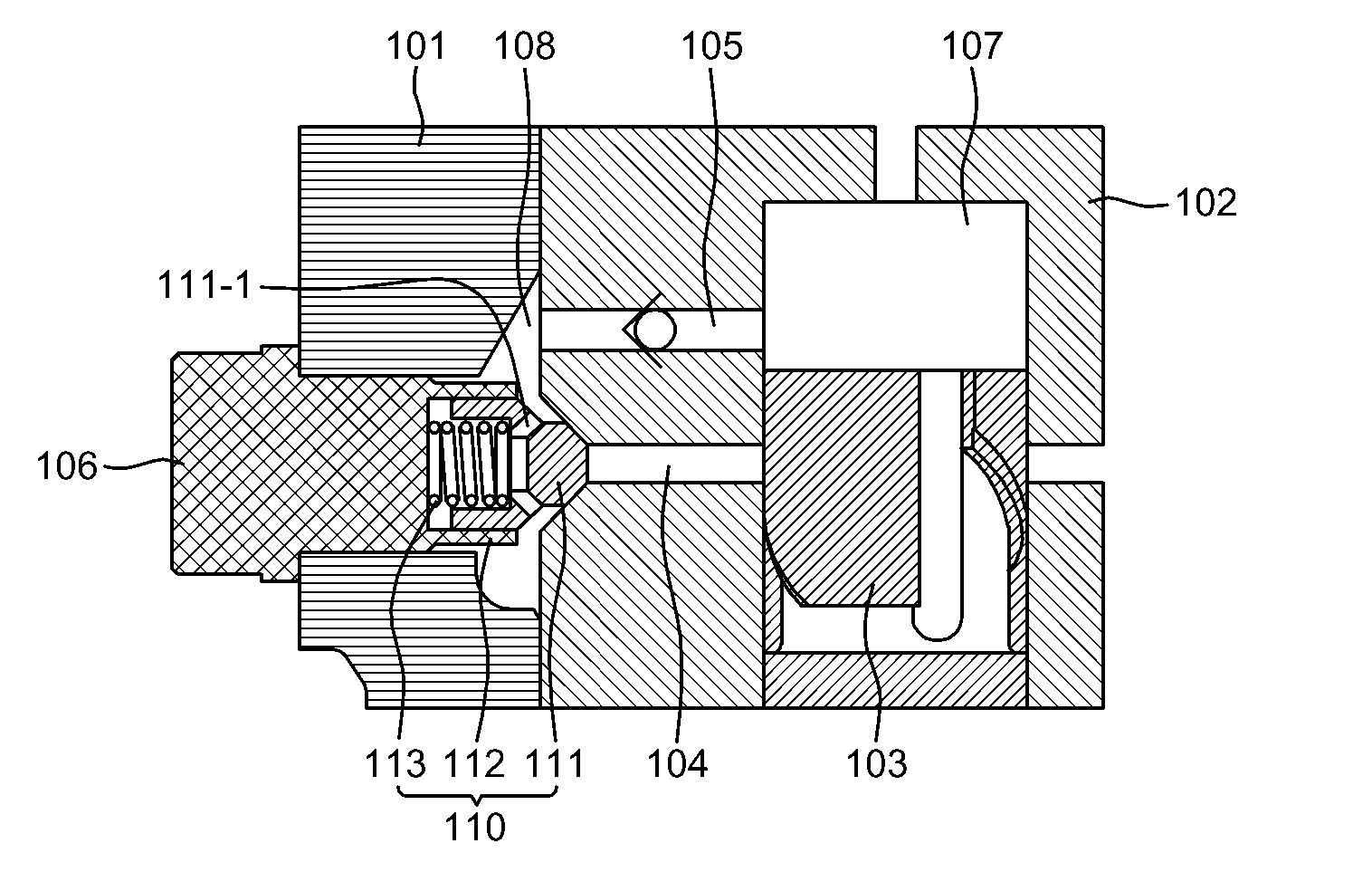
[0026]FIG. 5 is sectional view showing important parts of a fuel injection pump equipped with an apparatus for preventing cavitation damage according to the first embodiment of the present invention.

[0027]The apparatus for preventing cavitation damage according to the first embodiment of the present invention is applied to a fuel injection pump having a fuel intake valve 105 for the inflow of fuel and a barrel port 104 for the outflow of fuel. As such, the fuel injection pump having the fuel intake valve 105 and the barrel port 104 includes a fuel injection pump of a diesel engine that is mainly used for a large vessel. FIG. 5 shows the configuration wherein the fuel intake valve 105 is provided on a side surface of the fuel injection pump.

[0028]Meanwhile, the apparatus for preventing cavitation damage according to the first embodiment includes a pressure control valve 110 having a valve member 111, a valve housing 112, and a spring 113. The valve member 111 is disposed in the barre...

second embodiment

[0039]FIG. 7 is a sectional view showing important parts of a fuel injection pump equipped with an apparatus for preventing cavitation damage according to a second embodiment of the present invention. The cavitation damage preventing apparatus according to the second embodiment of the present invention is applied to a fuel injection pump that introduces and discharges fuel through a barrel port, in the case where the fuel injection pump has no fuel intake valve or it is required to introduce the fuel through the barrel port 104 so as to control a fuel injection time. Such a cavitation damage preventing apparatus according to the second embodiment includes a pressure control valve 210 that is mounted to open or close the barrel port 104, and a check valve 220 that is provided in the pressure control valve 210 to permit the inflow of fuel through the barrel port 104.

[0040]The pressure control valve 210 is disposed to open or close the barrel port 104, and includes a valve member 211 h...

third embodiment

[0043]FIG. 8 is a sectional view showing important parts of a fuel injection pump equipped with an apparatus for preventing cavitation damage according to a third embodiment of the present invention.

[0044]The cavitation damage preventing apparatus according to the third embodiment of the present invention is applied to a fuel injection pump which is difficult to ensure a space for mounting a check valve in a pressure control valve in an opposite direction thereof, although the fuel injection pump has no fuel intake valve or it is required to introduce the fuel through the barrel port 104 so as to control a fuel injection time as in the second embodiment. The cavitation damage preventing apparatus according to the third embodiment includes a pressure control valve 310 that is provided to open or close the barrel port 104, and a fuel inlet port 320 that is provided to be adjacent to the barrel port 104 shut by the pressure control valve 310, thus supplying the fuel from a fuel supply ...


PUM


Abstract

The present invention relates to an apparatus for preventing cavitation damage to a diesel engine fuel injection pump, wherein a pressure control valve for shutting a barrel port is mounted on a deflector or a barrel of the fuel injection pump to increase the fuel pressure in the barrel port during an early stage of fuel compression. This prevents fountain-type or jet-type cavitation from occurring before and after the opening of the barrel port during a late stage of fuel compression, thereby preventing corrosion damage caused by cavitation occurring mainly in a plunger and the barrel port of the fuel injection pump. The key technical features of the present invention are for an apparatus for preventing cavitation damage to a diesel engine fuel injection pump having a fuel intake valve and the barrel port for the inflow and outflow of fuel, respectively, comprising: a valve member mounted on the barrel port to shut the barrel port during an early stage of fuel compression performed by the upward movement of the plunger to increase the pressure in the barrel port; a valve housing installed in the deflector or the barrel of a pump housing to support the valve member; and a pressure control valve constituted by a spring interposed between the valve member and the valve housing to elastically support the valve member. The barrel port is shut to increase the pressure therein during the early stage of fuel compression, and thus preventing cavitation caused by the pressure difference between the barrel port and a pump chamber before and after the opening of the barrel port during the late stage of fuel compression. When the pressure of fuel in the barrel port exceeds a level higher than an open level, the barrel port opens to discharge fuel.

Description

TECHNICAL FIELD[0001]The present invention relates, in general, to an apparatus for preventing cavitation damage to a fuel injection pump of a diesel engine and, more particularly, to an apparatus for preventing cavitation damage to a fuel injection pump of a diesel engine, in which a pressure control valve is mounted to a surface of a deflector or a barrel of the fuel injection pump, thus preventing fountain- or jet-type cavitation from occurring before and after the opening of a barrel port during a late stage of fuel compression, thereby preventing damage caused by cavitation occurring mainly in a plunger and the barrel port.BACKGROUND ART[0002]Generally, diesel engines are internal combustion engines that draw air into a cylinder, compress the air to increase the temperature and pressure thereof, and inject a liquid fuel to the high temperature and high pressure air, thus causing spontaneous combustion and operating a piston, therefore obtaining power. The diesel engines may be ...

Claims


Application Information

Patent Timeline
Patent Type & Authority Applications(United States)
IPC IPC(8): F02M59/46
CPCF02M59/26F02M2200/04F02M63/005F02M59/265F02M59/44
Inventor KIM, DONG-HUNRYU, SEUNG-HYUPGHAL, SANG-HAKKANG, SANG-LIPKIM, JU-TAE
Owner HYUNDAI HEAVY IND CO LTD
Why Eureka
Try Eureka