Material Separator

Inactive Publication Date: 2011-10-27
EXPRESS ENERGY SERVICES OPERATING LP
View PDF12 Cites 10 Cited by
  • Summary
  • Abstract
  • Description
  • Claims
  • Application Information

AI Technical Summary

Benefits of technology

[0008]The current invention uses the naturally occurring gravitational separation of gases, fluids and solids in a manner that allows the materials to be quickly and efficiently removed from the system. By using this natural gravitational separation the assembly can be much smaller and much more efficient than any of the systems currently in operation. Under the current invention the separator is oriented at an angle to allow the materials which may include gas, fluid, and particulate materials to enter into the assembly on the high side of the assembly and travel along the length of the assembly. This orientation allows the gas to naturally separate from the liquid and sand. This also allows the gas to stay separated while traveling along the entire length of the assembly. Although the gas may travel at a higher velocity than the fluid this separa

Problems solved by technology

In addition some of the equipment can become damaged or plugged up when the sand settles out inside of the equipment piping or pipe lines.
This sand can also damage the equipment beyond repair or can result in costly and extensive cleaning operations to the piping and equipment.
The problem with this technology is, for the system to work the fluid has to be accelerated and directed to a flow path that causes a swirling affect that then slings the sand particles to the outside of the flow path.
These materials although resistant do not stop the abrasion and only prolong the wear.
Once however the components have been worn beyond their design tolerances they lose their effectiveness and the separators cease to work.
This failure can be unpredictable and catastrophic.
With new drilling technologies the current flow rates and pressures make this method of separation undesirable.
The problem with this technology is the higher the flow rate is, the larger the settling pot has to be for separation to occur.
Therefore these types of separators although robust are

Method used


Image

  • Material Separator
  • Material Separator
  • Material Separator

Examples


Embodiment Construction

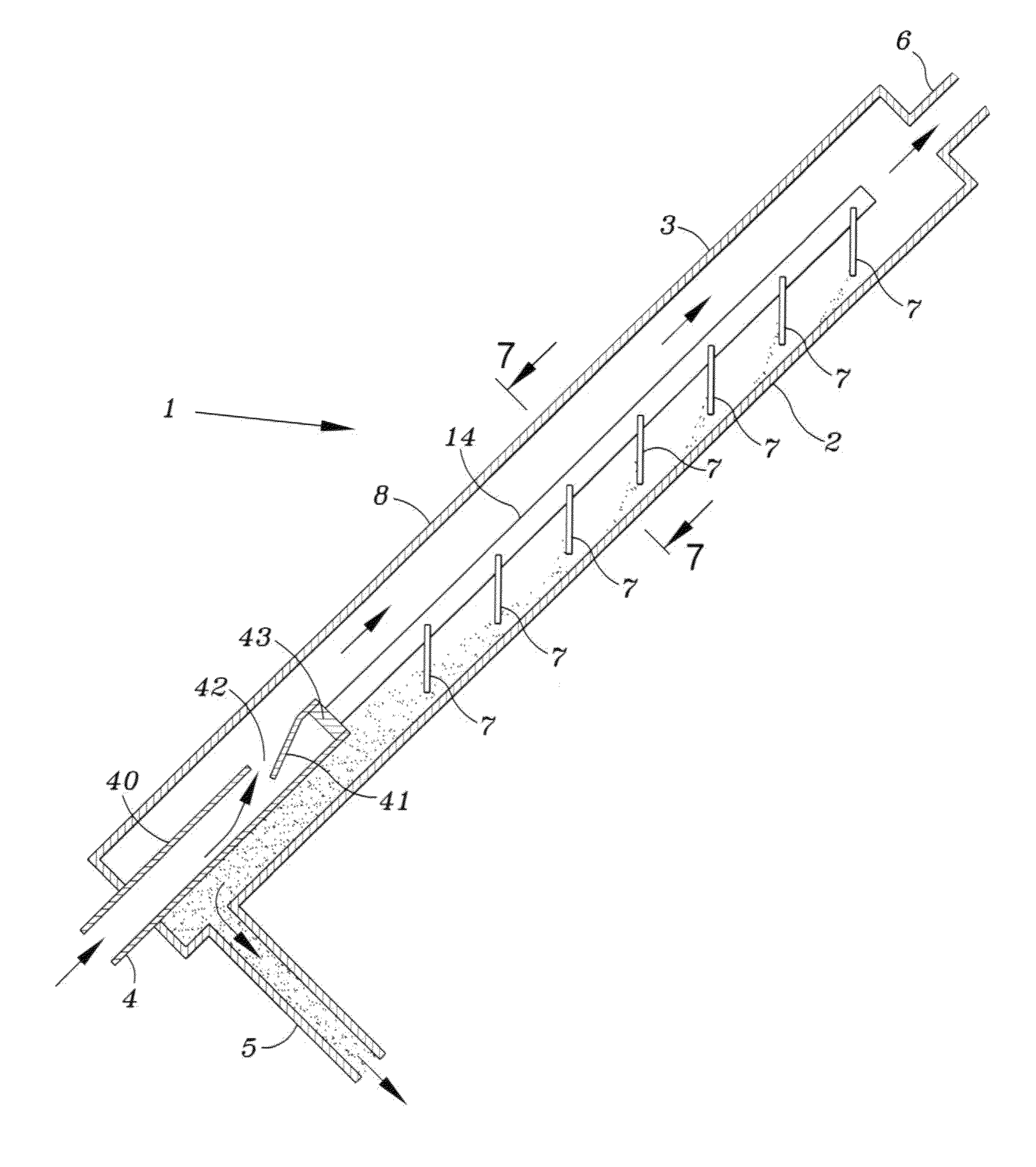
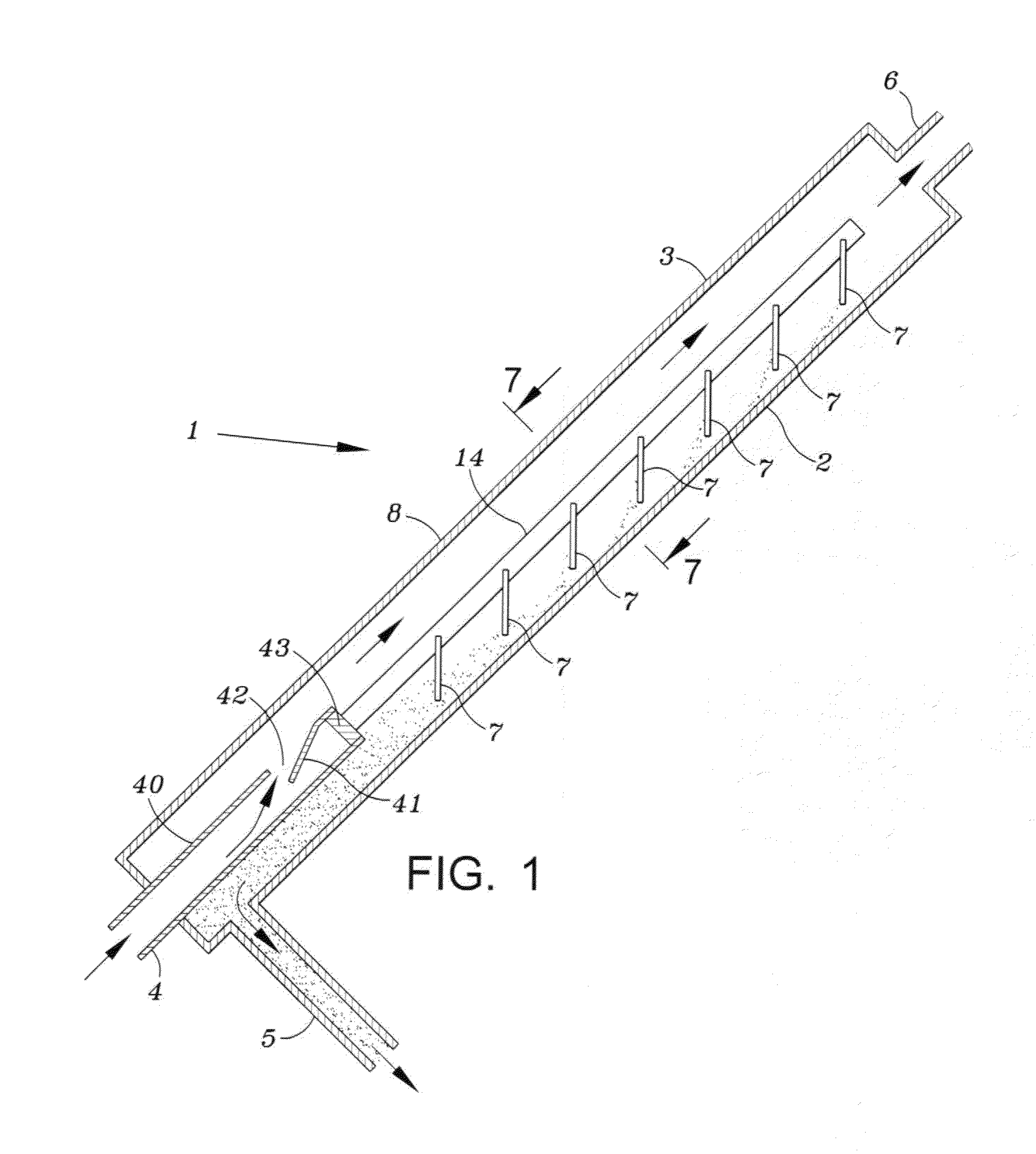
[0018]FIG. 1 illustrates an embodiment of the invention and shows a view of a separator 1. A plurality of separators may be connected to common manifolds for the input fluid, particle removal, and for the output fluid. The separator includes a first elongated body portion 8 having an upper side wall 3 and a lower side wall 2. In use the separator is inclined with respect to the horizontal at an angle of about, but not limited to, twenty to seventy degrees.

[0019]The separator body 8 may be a cylindrical tube having an inlet 4 at the lower portion, an outlet 5 in the lower portion for removal of the separated material, for example sand, and an outlet 6 in an upper portion for the liquid and any gas that may be present in the fluid introduced at the bottom of the body.

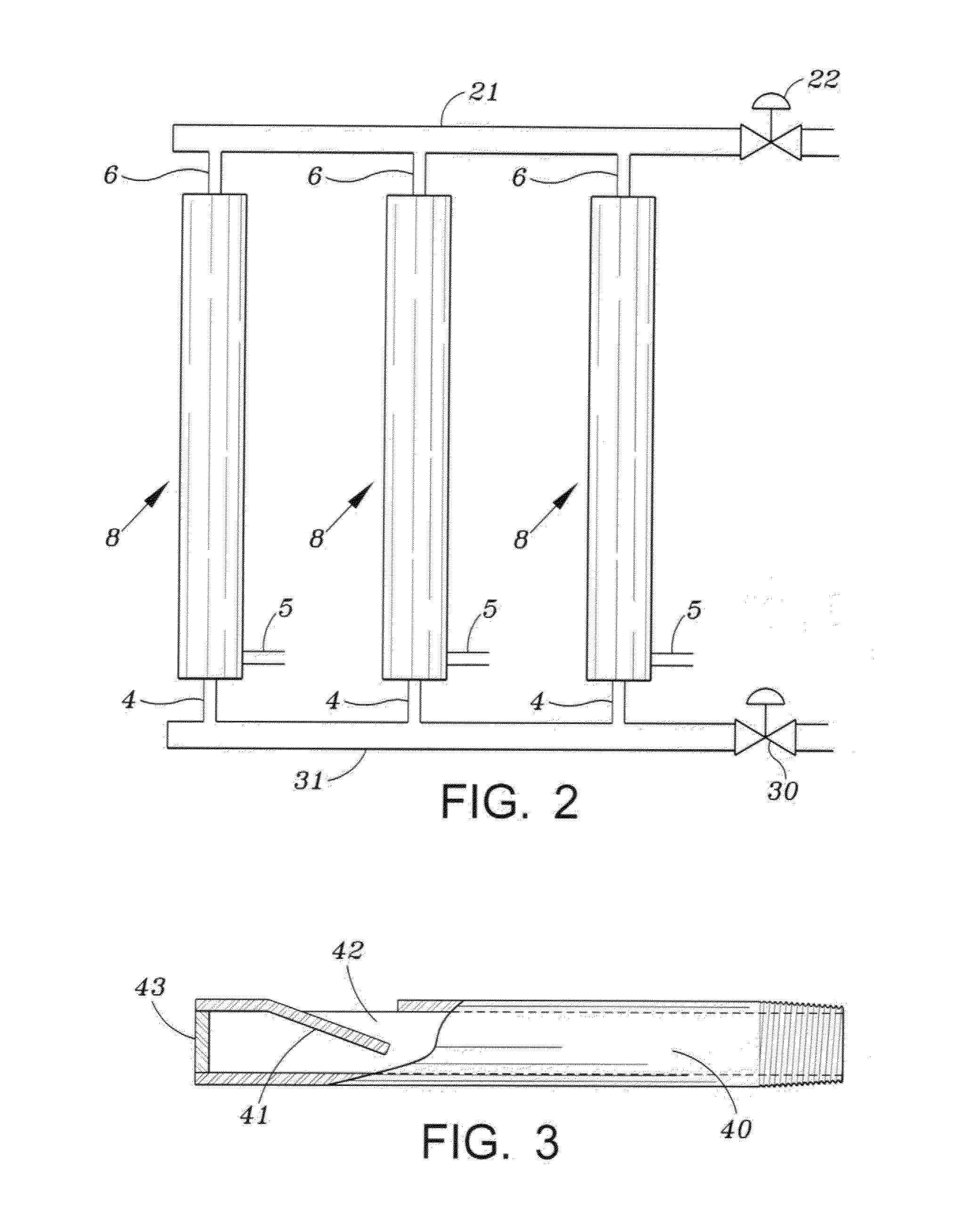
[0020]A cylindrical pipe 40 is connected to the inlet 4 and is secured within the body 8. As shown in FIGS. 3 and 5, the wall of the pipe has an outlet 42 formed by cutting a U-shaped slot in the wall and then bending the...


PUM

PropertyMeasurementUnit
Flow rateaaaaaaaaaa
Gravityaaaaaaaaaa
Velocityaaaaaaaaaa

Abstract

A material separator removes material such as sand from a fluid utilizing an inclined housing having a fluid flow inlet in a lower portion of the housing. Higher density material descends by gravity to a lower wall of the inclined housing and continues to travel down the lower wall portion to a lower section of the housing where it is removed. The remaining fluid which may contain a liquid and a gas is removed from the housing via an outlet at the upper portion of the housing.

Description

BACKGROUND OF THE INVENTION[0001]1. Field of Invention[0002]This invention is directed to a device for separating materials of different density, from a flowing stream of fluid which may contain solids, liquids and gases. The device may be readily transported to remote locations such as oil or gas wells to remove solids, for example sand, from fluid that is used at the well site for various purposes and requires treatment after use.[0003]2. Description of Related Art[0004]Currently sand separation equipment is used following fracturing or well stimulation operations. The sand separators are placed in line in front of the choke manifold and other production piping or equipment. This is done in an effort to avoid erosive damage that can be caused by the sand flowing at high velocities through the equipment. In addition some of the equipment can become damaged or plugged up when the sand settles out inside of the equipment piping or pipe lines. This sand can also damage the equipment b...

Claims


Application Information

Patent Timeline
IPC IPC(8): B01D43/00
CPCB01D21/0045B01D2221/04B01D45/02B01D21/0057
Inventor NOLES, JR., JERRY W.
Owner EXPRESS ENERGY SERVICES OPERATING LP
Why Eureka
Try Eureka