Power Supply Apparatus

a power supply and power supply technology, applied in the direction of switches, contact mechanisms, instruments, etc., can solve the problems of insufficient reduction of power consumption in low power mode or standby mode, high power requirement of the cpu on which the software is running, and limitations in varying the level of power supplied, so as to reduce the circuit area and costs, minimize the increase in circuit scale, and high power

Inactive Publication Date: 2011-10-27
OITA UNIVERSITY
View PDF1 Cites 52 Cited by
  • Summary
  • Abstract
  • Description
  • Claims
  • Application Information

AI Technical Summary

Benefits of technology

[0036]The power supply apparatus of the present invention can supply high power and low power to a load circuit in a switchable manner in accordance with the needs of the load circuit while minimizing an increase in circuit scale. This obviously reduces the circuit area and costs, and thus a power supply apparatus that can efficiently cover a wide range of loads from light load to heavy load can be provided.
[0037]In addition, by the use of the driver contained in the switching power source which is designed in consideration of noise effects, it is hardly affected by noise.

Problems solved by technology

For example, when the software is performing only a display function, the CPU on which the software is running requires low power, while, when the software is performing calculations, the CPU on which the software is running requires high power.
A power supply apparatus with such a configuration could vary the level of power supplied to the load circuit only to a limited extent and could not sufficiently reduce power consumption in the low power mode or standby mode.
In a power supply apparatus with such a configuration, there were limitations in varying a level of power supplied to the load circuit, and it was impossible to sufficiently reduce power consumption in the low power mode or standby mode.
Another problem particularly associated with switching power sources is that, since the main circuit unit that transmits electrical power to a load is designed to have device characteristics suited for heavy load applications that require a large load current, it is difficult to improve power efficiency of the main circuit unit for light load applications that require only a small load current.

Method used


Image

  • Power Supply Apparatus
  • Power Supply Apparatus
  • Power Supply Apparatus

Examples


embodiment 1

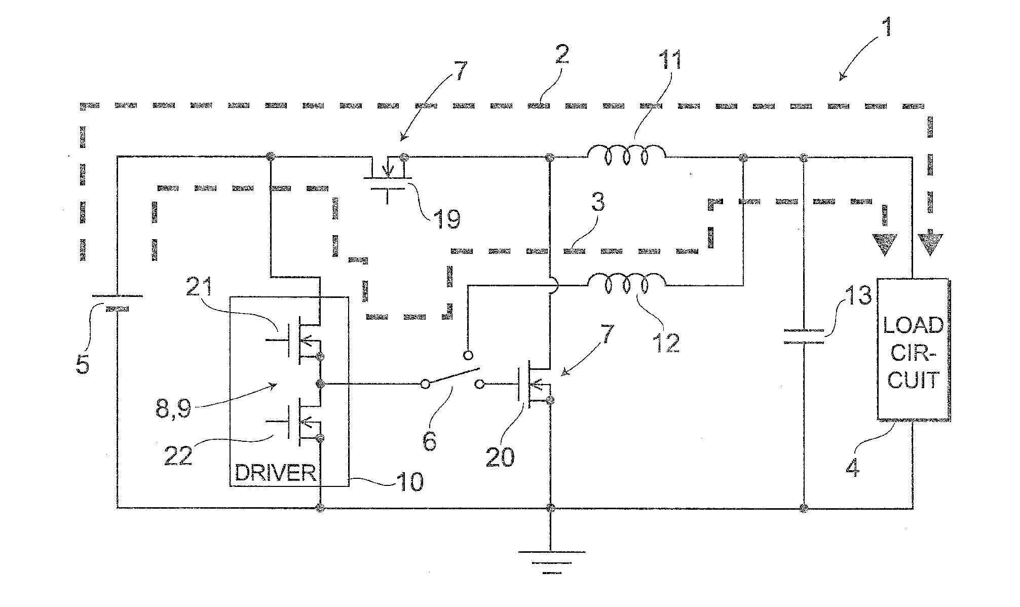
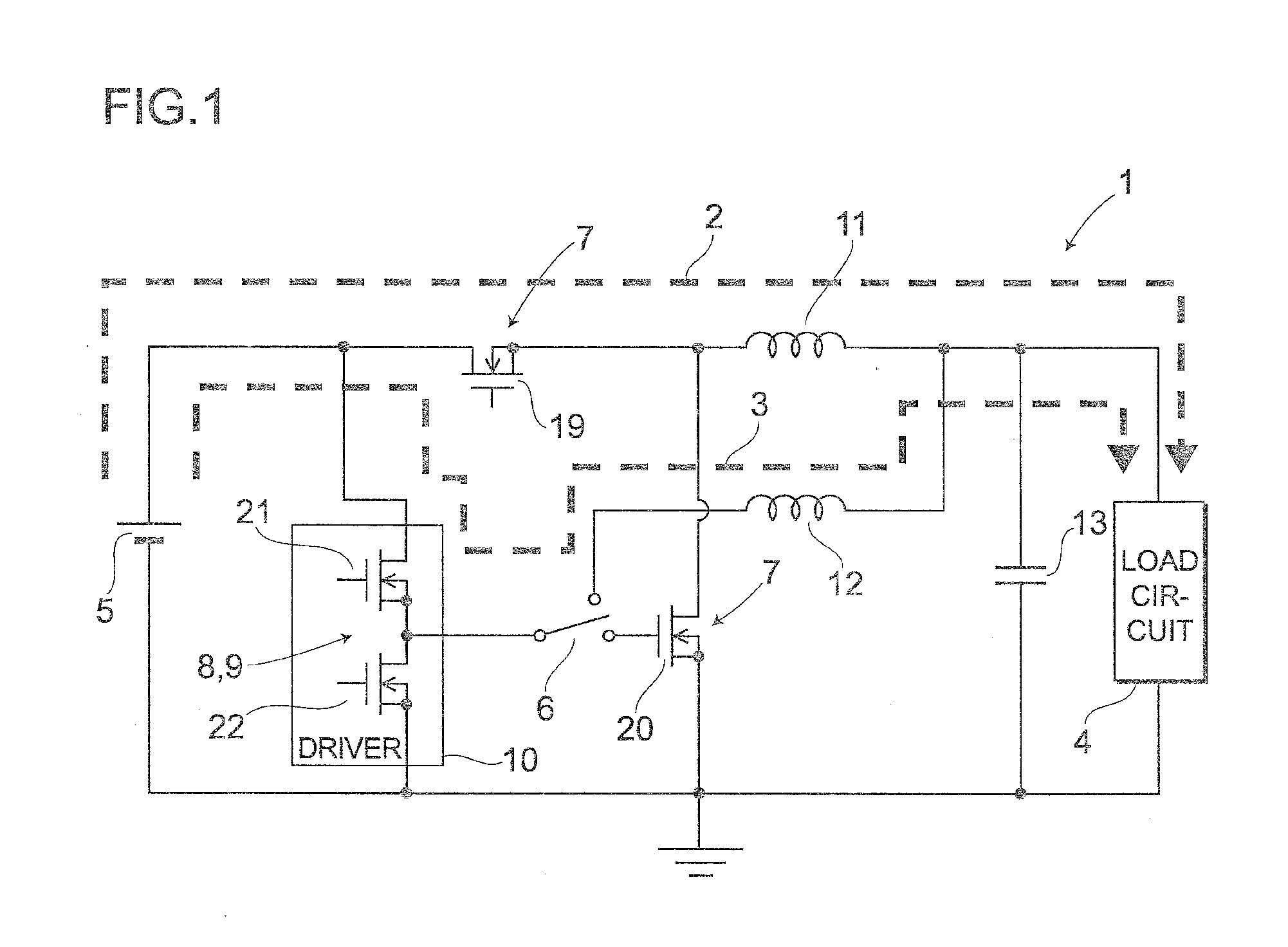
[0057]First, the overall structure of the power supply apparatus according to a first embodiment will be described with reference to FIG. 1. FIG. 1 is a circuit diagram of the power supply apparatus applied to a step-down converter in the first embodiment of the invention.

(Overall Structure)

[0058]The power supply apparatus 1 includes a power source 5 that supplies power to a load circuit 4 via one of a first path 2 and a second path 3, a switching unit 6 that switches between the first path 2 and the second path 3, a first switch 7 that controls a first level of power supplied via the first path 2, an open / close switch 8 that controls timing of the opening and closing of the first switch 7, a driver 10 including the open / close switch 8, and a second switch 9 that controls a second level of power supplied via the second path 3. The open / close switch 8 and the second switch 9 are an identical, common element.

[0059]The power supply apparatus 1 further includes, as a filter for smoothin...

second embodiment

[0162]Next, the second embodiment will be described. In the second embodiment, the power supply apparatus applied to a step-down converter will be described with reference to FIG. 8 to FIG. 12, giving more specific examples of circuits.

[0163]FIG. 8 to FIG. 12 are block diagrams of the power supply apparatus according to the second embodiment of the invention. Each of FIG. 8 to FIG. 12 illustrates the circuit diagram having the same circuit configuration in different operation states. How a power supply apparatus 50 operates can be explained by all of FIG. 8 to FIG. 12.

[0164](1) FIG. 8 illustrates a state in which a switching unit 56 has not selected either of a first path 52 and a second path 53. It shows the circuit diagram common to FIG. 8 to FIG. 12.

[0165](2) FIG. 9 illustrates a state in which the switching unit 56 has selected the first path 52 so that power is supplied from a power source 55 to a load circuit 54 via the first path 52. In particular, it shows the period in whic...

third embodiment

[0224]Next, a third embodiment will be described with reference to the circuit diagram of FIG. 13. As shown in the drawing, in this power supply apparatus 50 shown here, the first inductor Lm and the second inductor Ls described in the second embodiment above are formed as a common inductor Lms.

[0225]Here, as a main circuit of the power supply apparatus 50, a step-down converter 75 is provided, which includes MOS transistors Sm and SR that form the first switch 57, and the inductor Lms that serves as a means for accumulating and discharging energy, for generating an output voltage lower than the input voltage Vi of the power source 55 and for supplying the voltage to the output capacitor Co and the load circuit 54 by the switching operation of the MOS transistors Sm and SR. The step-down converter 75 itself is provided also in the first and second embodiments described above. In this embodiment, in particular, the first inductor Lm interposed in the first path 52 and the second indu...


PUM


Abstract

To provide a power supply apparatus that can supply a large current and a small current to a load circuit in a switchable manner, with a minimum circuit scale and an efficient use of electronic devices and elements contained in conventionally used power supply apparatuses. The power supply apparatus 1 includes a power source 5 that supplies power to a load circuit 4 via one of a first path 2 and a second path 3, a switching unit 6 that switches between the first path 2 and the second path 3, a first switch 7 that controls a supply period that provides a reference for a first level of power supplied via the first path 2, a driver 10 including an open / close switch 8 that controls timing of opening and closing of the first switch 7, and a second switch 9 that controls a supply period that provides a reference for a second level of power supplied via the second path 3, wherein the first level of power is higher than the second level of power, the first path 2 runs through outside of the driver 10 while the second path 3 runs through inside of the driver, and the open / close switch 8 and the second switch 9 are a common element.

Description

TECHNICAL FIELD[0001]The present invention relates to a power supply apparatus capable of supplying power to a load circuit while switching levels of power being supplied, the invention being applicable to, for example, power supply circuits, switching power sources, and switching power source circuits.BACKGROUND ART[0002]Conventionally, power supply apparatuses such as switching power sources or power supply circuits that supply electrical power (voltage or current) from a power source to a load circuit have been used in electronic circuits or electronic equipments. Such power supply apparatus may be implemented, for example, as DC-DC converter devices.[0003]Electronic equipments in recent years have been desired to have lower power consumption and standby power requirement. Load circuit operations include some modes that require high power and other modes that require low power. In particular, most electronic equipments include a central processing unit (hereinafter referred to as...

Claims


Application Information

Patent Timeline
Patent Type & Authority Applications(United States)
IPC IPC(8): G05F3/02
CPCH02M3/1584H02M3/157
Inventor NISHIJIMA, KIMIHIRO
Owner OITA UNIVERSITY
Why Eureka
Try Eureka