
Capping Layer for Insulator in Micro-Fluid Ejection Heads

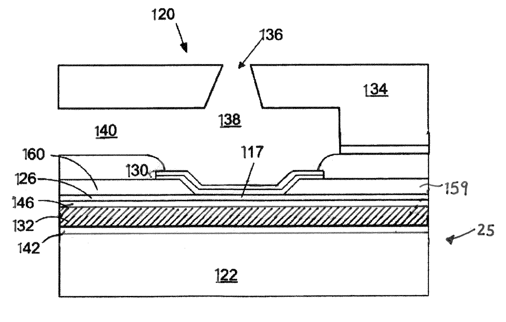
a technology of insulating layer and micro-fluid ejection head, which is applied in printing and other directions, can solve the problems of low thermal efficiency of micro-fluid ejection head and resistance instability over a long term life of the head, and achieve the effect of improving adhesion

Inactive Publication Date: 2011-10-27
FUNAI ELECTRIC CO LTD
View PDF2 Cites 3 Cited by
  • Summary
  • Abstract
  • Description
  • Claims
  • Application Information

AI Technical Summary

Benefits of technology

The patent text describes a solution for improving the performance of micro-fluid ejection heads used in printers. The solution involves applying a capping layer to the insulators in the heads. The capping layer can be made of methyl silesquioxane or silicon nitride and acts as a protective barrier, improving adhesion between the insulator and the resistor layer. The thickness of the capping layer ranges from 5000-6000 Angstroms to a few Angstroms to about 2000 Angstroms. The patent also mentions that plasma treatments can be applied to the insulator layer to passivate the surface and seal off its pores. The technical effects of this solution include improved thermal stability and better adhesion between the insulator and the resistor layer, leading to improved performance of the micro-fluid ejection heads.

Problems solved by technology

While the design has proved adequate over the years, significant heat absorption from the heaters still remains in modern designs which keeps low the thermal efficiency of the micro-fluid ejection head.
During recent wafer qualification testing, however, the inventors have observed that direct contact between the MSQ and the resistor layer results in resistance instability over a long term life of the head.

Method used


Image

  • Capping Layer for Insulator in Micro-Fluid Ejection Heads
  • Capping Layer for Insulator in Micro-Fluid Ejection Heads
  • Capping Layer for Insulator in Micro-Fluid Ejection Heads

Examples


Embodiment Construction

[0016]In the following detailed description, reference is made to the accompanying drawings where like numerals represent like details. The embodiments are described in sufficient detail to enable those skilled in the art to practice the invention. It is to be understood that other embodiments may be utilized and that process, electrical, and mechanical changes, etc., may be made without departing from the scope of the invention. Also, the term wafer or substrate includes any base semiconductor structure such as silicon-on-sapphire (SOS) technology, silicon-on-insulator (SOI) technology, thin film transistor (TFT) technology, doped and undoped semiconductors, epitaxial layers of silicon supported by a base semiconductor structure, as well as other semiconductor structures hereafter devised or already known in the art. The following detailed description, therefore, is not to be taken in a limiting sense and the scope of the invention is defined only by the appended claims and their e...


PUM


Abstract

A micro-fluid ejection head has a resistor layer defining a heater element. An insulative layer underlies the heater element and a capping layer on the insulative layer substantially prevents ion mobility between the resistor and insulative layers. Resistance stability of the heater has been shown improved as has adhesion of the heater to the insulator. Representative layers include insulation of methyl silesquioxane (MSQ) in a thickness of about 5000 Angstroms or more, while the cap is a silicon nitride in a thickness of about 2000 Angstroms or less. Other capping layers include silicon carbide, silicon oxide or dielectrics. The resistor layer typifies TaAIN in a thickness of about 350 Angstroms, including overlying anode and cathode conductors that define the heater. Coating layers are also disclosed as are thermal barrier layers.

Description

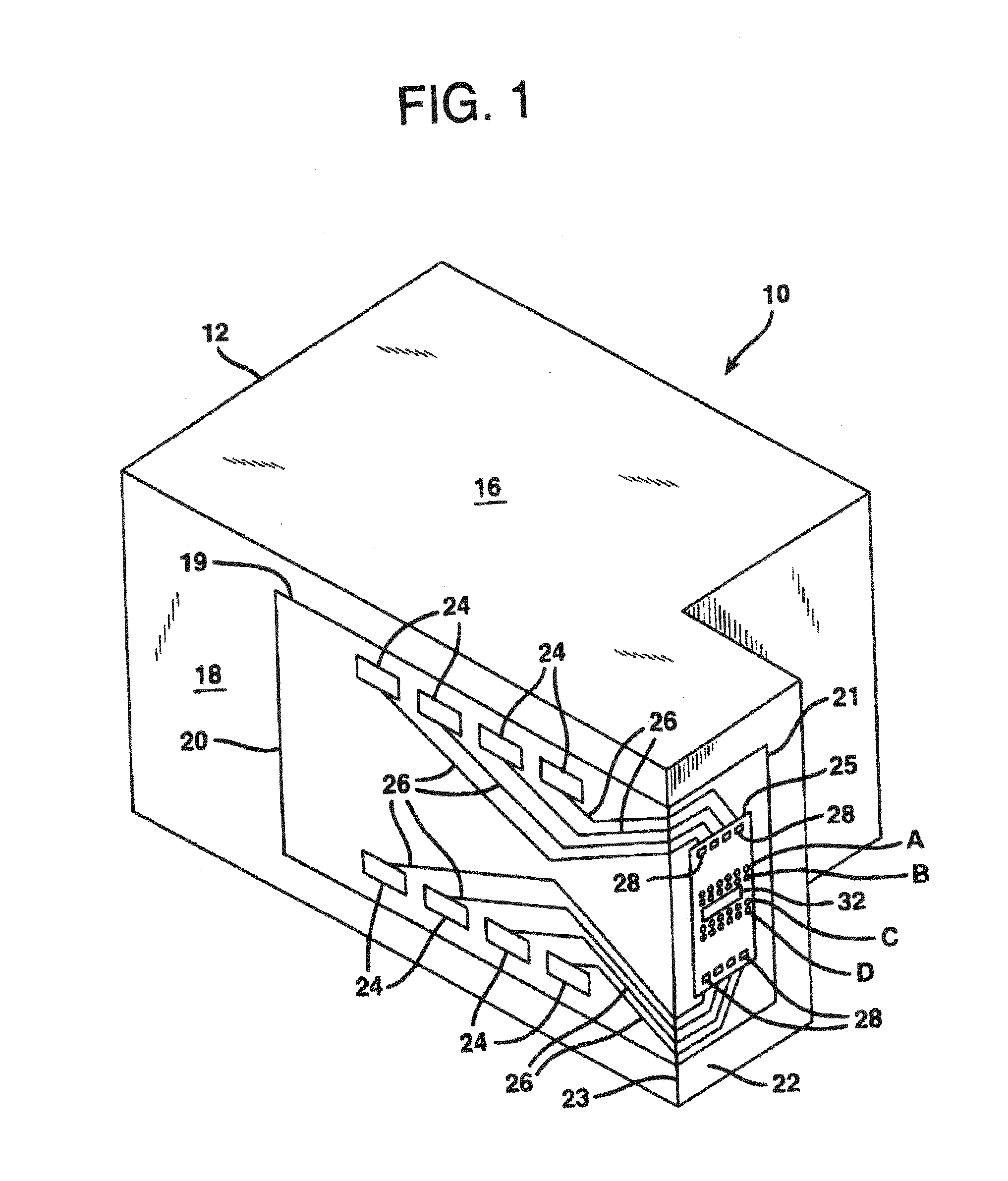
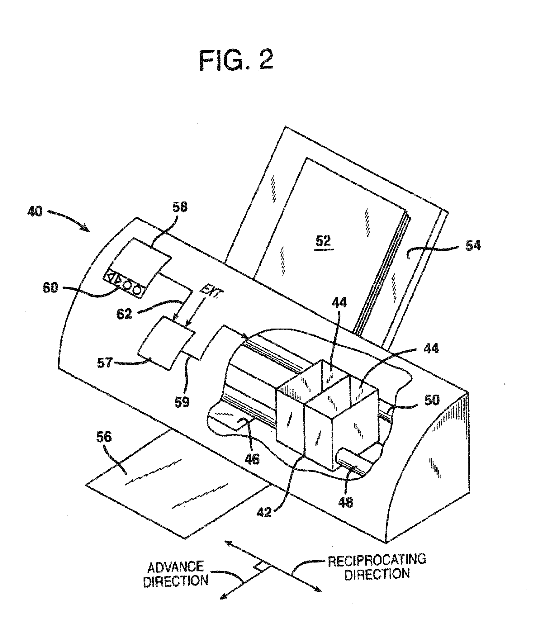
FIELD OF THE INVENTION[0001]The present invention relates to micro-fluid ejection heads, such as inkjet printer actuation devices. More particularly, although not exclusively, it relates to insulating the devices to improve energy efficiency, including capping layers to stabilize resistivity.BACKGROUND OF THE INVENTION[0002]The art of printing images with micro-fluid technology is relatively well known. Familiar devices include fax machines, all-in-ones, inkjet printers, and graphics plotters, to name a few. Conventionally, an ejection head in an inkjet printer includes access to a local or remote supply of ink, a heater chip, a nozzle plate, and an input / output connector, such as a tape automated bond (TAB) circuit. The TAB circuit electrically connects the heater chip to the printer. The heater chip typifies thin film resistors or heaters fabricated by growing, forming, depositing, patterning and etching various layers on a substrate, such as a silicon wafer. One or more ink vias ...

Claims


Application Information

Patent Timeline
Patent Type & Authority Applications(United States)
IPC IPC(8): B41J2/05
CPCB41J2002/14387B41J2/14129
Inventor GUAN, YIMINJOYNER, II, BURTON L.
Owner FUNAI ELECTRIC CO LTD
Learn More