Method of Producing Laminated Body, and Laminated Body

a technology applied in the field of laminated body and body, can solve the problems of deteriorating work efficiency, affecting the quality of laminated body, and requiring workers considerable force and time, and achieves superior effect, improved handling ability, and easy peeling.

Inactive Publication Date: 2011-10-27
JX NIPPON MINING& METALS CORP
View PDF7 Cites 11 Cited by
  • Summary
  • Abstract
  • Description
  • Claims
  • Application Information

AI Technical Summary

Benefits of technology

[0035]The carrier-attached metal foil of the present invention is a rectangular laminated body in which a carrier A and a metal foil B alternately overlap, wherein proof stress or yield stress of the carrier A is 20 to 500 N / mm2, and the carrier A and the metal foil B are bonded at ends of two facing sides with an adhesive having an adhesive strength of 5 g / cm to 500 g / cm. Thus, the worker's handling ability will improve, and peeling can also be performed easily. In addition, it is possible to provide a production method that is free from wrinkles, cracks and peeling in the air-vent process. Moreover, since the misalignment of the circuit will not occur, the present invention yields a superior effect of being able to reduce defective products and thereby improve the production yield.

Problems solved by technology

Here, with the carrier-attached copper foil to be used, since the ultrathin copper foil and the carrier are bonded across the entire surface, there is a problem in that peeling the carrier after lamination requires the worker considerable force and much time (refer to Patent Document 9).
In addition, as described above, upon performing the lay-up (lamination assembly) operation, the worker needs to alternatively repeat the process of lamination so that the M surface of the copper foil is on top or the M surface is at the bottom, and there is a problem in that the work efficiency will deteriorate.
Moreover, since the copper foil and the carrier are of the same size, it is difficult to peel one copper foil at a time during the lay-up, and there is also a problem in that the workability deteriorates with respect to this point.
This will lead to the misalignment of the circuit in the in-plane direction, and there is a problem in that this will become a cause for deteriorating the production yield.
Even upon producing this carrier foil and copper foil bonded body in which two sides are bonded and fixed via ultrasonic welding or the like, the air-vent process is required as with the other foregoing documents, but it is difficult to vent air without creating wrinkles.
The reason for this is that, pursuant to the misalignment between the sheets upon pressing the sheets with a rotary roller and squeezing out air, stress is accumulated at the fixed bond part to which no misalignment will occur, and will be subject to defects such as wrinkles or cracks.
Nevertheless, a rigid carrier also entails its own problem, Specifically, since the carrier is highly rigid, when the bonding is performed in an easily peelable manner, the copper foil and carrier will instantaneously become separated and then undergo deflection during the handling or the like, and air is sucked into the gap.
Thus, dust and foreign matter get sucked into the gap.
In other words, a rigid carrier has a problem in that it is subject to a bellows effect.
Moreover, Patent Document 9 proposes a carrier-attached copper foil that is configured to be bonded across its entire surface, but in this case there is a problem in that the peeling strength will rise and the peeling process will become difficult.
There is also a problem in that deflection will occur during the handling thereof and air and foreign matter get mixed in from the portion that is bonded weakly due to the foregoing deflection.

Method used


Image

  • Method of Producing Laminated Body, and Laminated Body
  • Method of Producing Laminated Body, and Laminated Body
  • Method of Producing Laminated Body, and Laminated Body

Examples


example 1

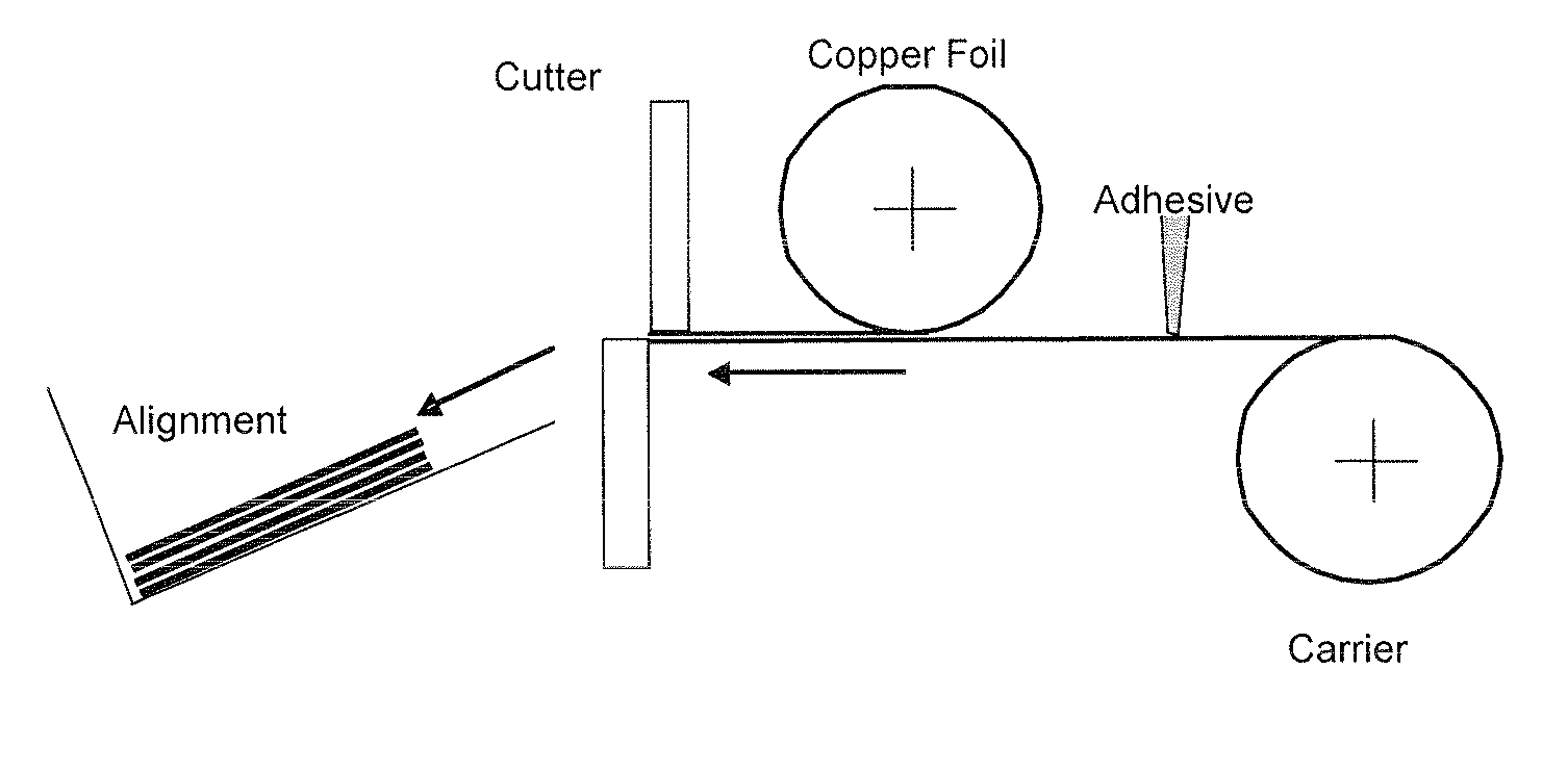
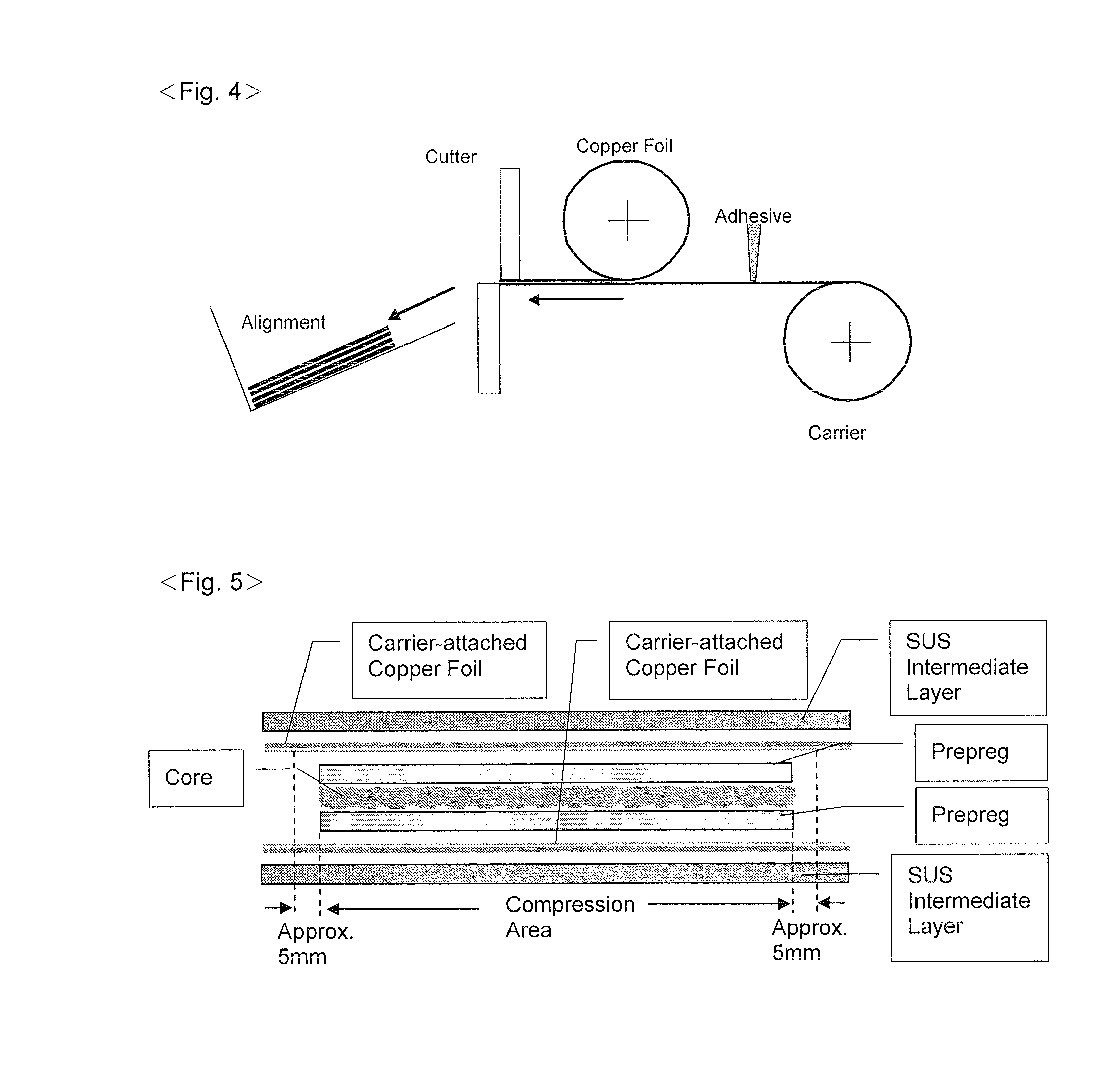
[0118]An aluminum foil of 40 μm was used as the carrier A, and a copper foil of 35 μm was used as the foil to be bonded thereto. An adhesive with a viscosity of 2,000,000 to 3,000,000 mPA·S was used, and applied at an application width of 3 mm at both facing ends while winding off the carrier A from a bobbin. The adhesive was applied linearly.

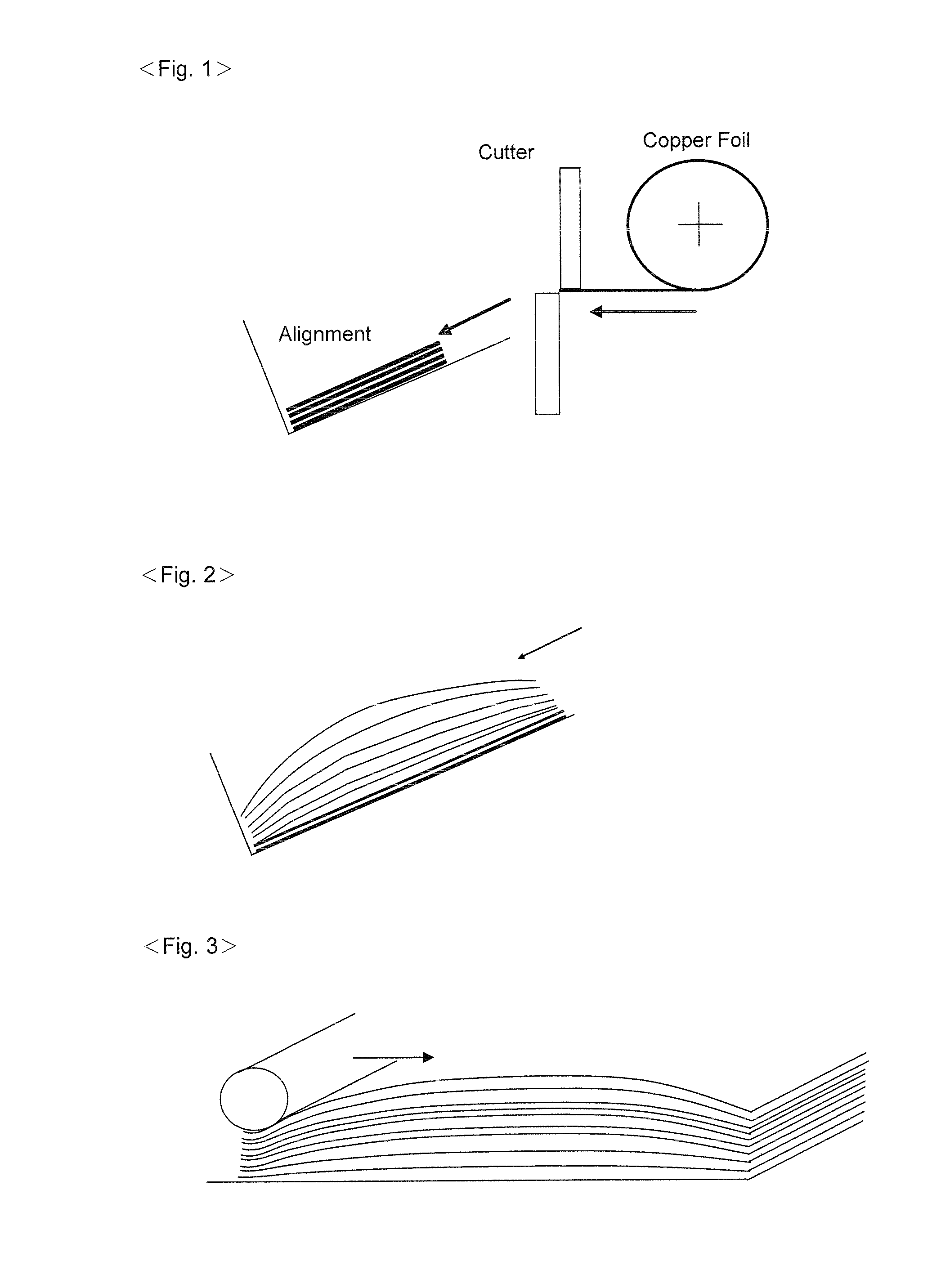
[0119]The metal foil B was laid on and bonded to a side to which the adhesive was applied while being wound off from a bobbin, the obtained laminated body was subsequently cut, the cut laminated bodies were aligned, and a roller was applied from the top of an object to be cut (air-vent).

[0120]Consequently, bonding was possible in a state that is free from the generation of wrinkles and cracks with the viscosity being 2,000,000 to 3,000,000 mPA·S.

[0121]When the viscosity was 5,000,000 mPA·S, wrinkles occurred and the laminated body became defective.

example 2

[0122]An aluminum foil of 12 μm was used as the carrier A, and a copper foil of 9 μm was used as the foil to be bonded thereto. An adhesive with a viscosity of 800,000 to 900,000 mPA·S was used, and applied at an application width of 3 mm. The adhesive was applied linearly. The process from bonding to roller application was the same as Example 1.

[0123]Since the carrier and the copper foil were thin, bonding was possible in a state that is free from the generation of wrinkles and cracks with the viscosity being 800,000 to 900,000 mPA·S, which is a range that is smaller than Example 1, even though some lenticulation could be observed.

[0124]Meanwhile, when the viscosity was 2,000,000 mPa·S, wrinkles occurred and the laminated body became defective.

[0125]Accordingly, it has been confirmed that it is necessary to adjust the viscosity of the adhesive to be applied depending on the material and thickness of the carrier A.

example 3

[0126]An aluminum foil of 18 μm was used as the carrier A, and a copper foil of 5 μm was used as the foil to be bonded thereto. An adhesive was applied linearly at an application width of 3 mm. The process from bonding to roller application was the same as Example 1.

[0127]In the foregoing case, since the copper foil was even thinner than Example 2, bonding was possible in a state that is free from the generation of wrinkles and cracks with the viscosity being 8000 to 10000 mPA·S, even though some lenticulation could be observed.

[0128]Meanwhile, when the viscosity was 1,500,000 mPA·S, wrinkles occurred and the laminated body became defective.

[0129]Accordingly, in this case also, it has been confirmed that it is necessary to adjust the viscosity of the adhesive to be applied depending on the material and thickness of the carrier A.


PUM

PropertyMeasurementUnit
yield stressaaaaaaaaaa
thicknessaaaaaaaaaa
thicknessaaaaaaaaaa

Abstract

Provided is a method of producing a laminated body, wherein, while winding off a carrier A from a bobbin, an adhesive is applied to both facing ends thereof, a metal foil B is laid on and bonded to a side to which the adhesive was applied while being wound off from a bobbin, the obtained laminated body is subsequently cut, the cut laminated bodies are aligned, a roller is applied from the top of an object to be cut configured from the aligned laminated bodies when the elevation of the center of the object to be cut becomes high to vent air existing between the objects to be cut and in the laminated bodies, and the adhesive is eventually hardened to mutually bond the laminated bodies. In particular, this invention provides a carrier-attached copper foil to be used upon producing a laminated plate, and aims to realize the improvement in the handling ability in the production process of a printed board and cost reduction based on an improved production yield.

Description

TECHNICAL FIELD[0001]The present invention relates to a method of producing a laminated body configured from a carrier-attached copper foil that is used in producing a single-sided or multilayer laminated body of two or more layers for use in a print wiring board, and also relates to a laminated body obtained thereby.BACKGROUND ART[0002]A typical example of a multilayer laminated body is a printed circuit board. Generally, a printed circuit board is basically configured from a dielectric material referred to as a “prepreg” that is obtained by impregnating synthetic resin in a base material such as a synthetic resin plate, glass plate, nonwoven glass fabric or paper.[0003]A sheet such as a copper or copper alloy foil having electrical conductivity is bonded to the prepreg surface (front and back surfaces). A laminate that is assembled as described above is generally referred to as a CCL (Copper Clad Laminate) material. When copper foils are multi-layered on the CCL material via the p...

Claims


Application Information

Patent Timeline
Patent Type & Authority Applications(United States)
IPC IPC(8): B32B7/14B32B15/08B32B37/16B32B38/10B32B37/02B32B37/12
CPCB32B37/0007Y10T428/24826B32B37/1292B32B38/0004B32B2307/54B32B2309/105B32B2311/12B32B2457/08B65H2301/4223B65H2601/211H05K3/025H05K2203/0143H05K2203/0228H05K2203/068H05K2203/1178B32B37/003Y10T156/1052Y10T428/24917B32B37/0076B32B15/00B32B37/12B32B37/20B32B38/0012B32B37/1284H05K3/00H05K3/4611
Inventor TAKAMORI, MASAYUKI
Owner JX NIPPON MINING& METALS CORP
Why Eureka
Try Eureka