Hemodialysis grafts and methods for localizing and identifying the placement of same

a technology for hemodialysis and vascular grafts, which is applied in the field of improving the construction of vascular access grafts, can solve the problems of multiple needle-puncture procedures to access grafts, hematomas can result from uncontrolled bleeding, and damage to grafts, so as to facilitate easy, accurate and reproducible entry and improve the access to an implanted graft device. , the effect of improving the access

Inactive Publication Date: 2011-10-27
THE METHODIST HOSPITAL RES INST
View PDF5 Cites 31 Cited by
  • Summary
  • Abstract
  • Description
  • Claims
  • Application Information

AI Technical Summary

Benefits of technology

[0014]In view of these and other shortcomings of the prior art, the present invention provides new methods and devices that may advantageously improve access to an implanted graft device (e.g., an arterio-venous (AV) g

Problems solved by technology

Because hemodialysis patients undergo repetitive, often painful, large-needle punctures of their skin and underlying tissue numerous times per week to gain entry into surgically implanted AVGs, these implants typically remain patent (and unobstructed) for several months to several years, and must periodically be repaired or replaced.
The disadvantages of multiple needle-puncture procedures to access the graft are numerous and well documented.
First, hematomas can result from uncontrolled bleeding.
Second, grafts can be damaged by the multiple punctures required for routine dialysis.
Third, the threat of physical damage to the graft itself, and/or infection at the cannulation site can destroy the integrity of the access graft.
Complications with the graft can ultimately lead to poor, inadequate, or incomplete functioning, or, alternatively, to thrombus formation, which, in most cases, results in the need for additional surgical intervention, including, e.g., repair or replacement of the graft, and/or resection of the resultant clots and/or traumatized tissue.
These repeated punctures of the graft material, however, are prone to error and complication.
The formation of such blood clots may result not only in multiple graft thromboses, but may eventually lead to graft failure.
Another significant limitation is “finding” the proper posi

Method used


Image

  • Hemodialysis grafts and methods for localizing and identifying the placement of same
  • Hemodialysis grafts and methods for localizing and identifying the placement of same
  • Hemodialysis grafts and methods for localizing and identifying the placement of same

Examples


example 1

Construction of a Magnetically-Localizable Graft Device

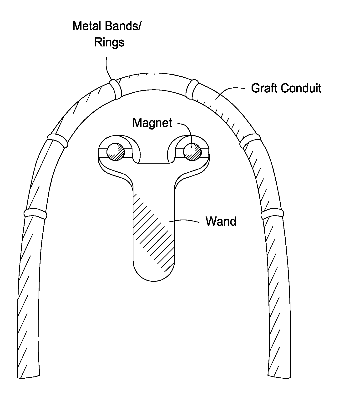
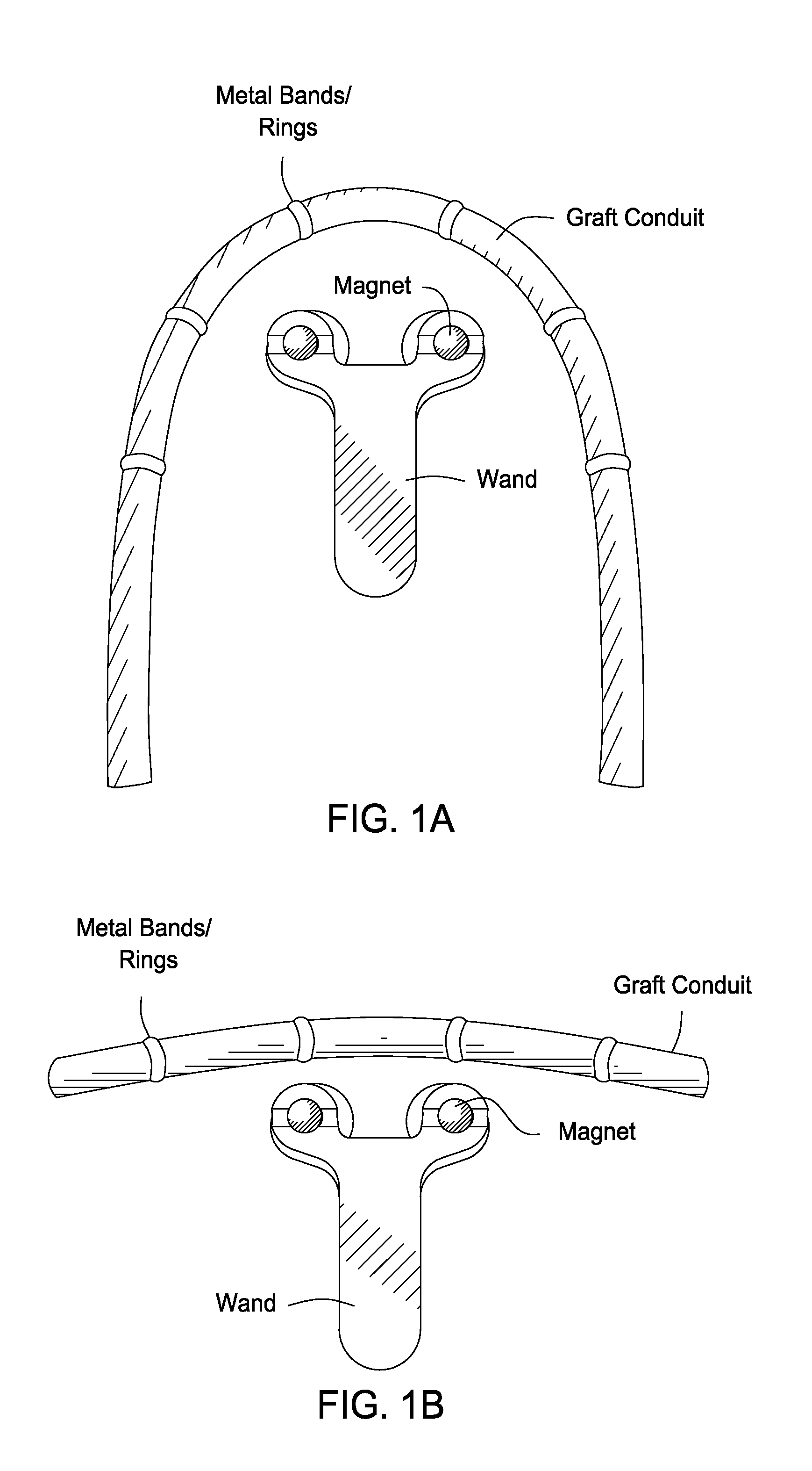
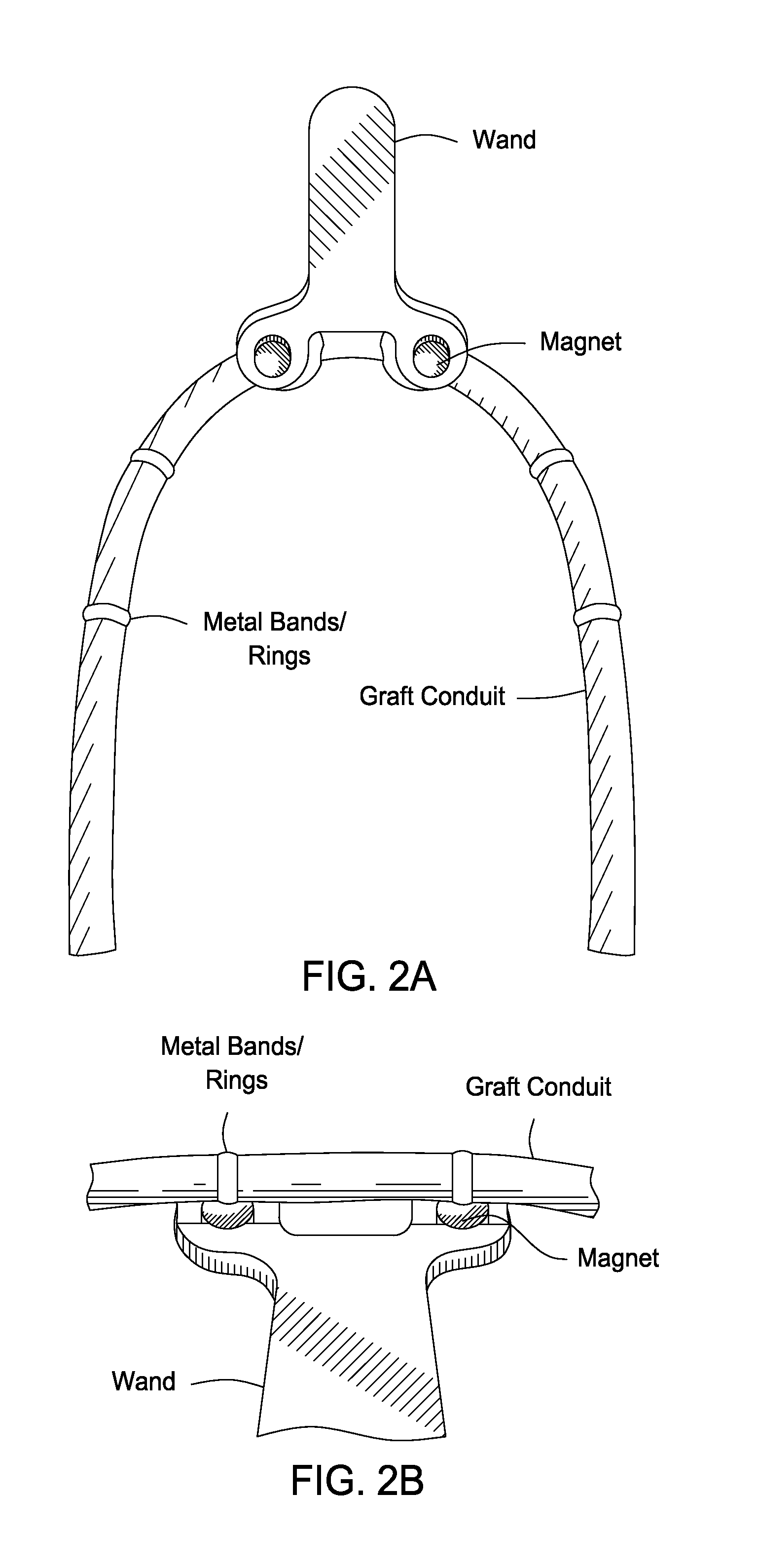
[0137]A prototype magnetically localizable graft device was constructed that had six magnetic bands spaced at 4-cm intervals (center to center) along the graft length. The bands were held in position, and chaffed using ePTFE with approximately 1 to 1½ mm overlap of the edges. The assembled graft contained a single layer of ePTFE tape that was spiral wound onto the graft with minimal overlap of the layer (see, e.g., FIG. 1A, FIG. 1B, FIG. 2A, FIG. 2B, FIG. 2C, FIG. 2D, FIG. 3A, and FIG. 3B).

[0138]The bands were constructed from 0.006-inch thick Series 420 surgical stainless steel. The chaffing utilized was 0.0025-inch thick ePTFE cut into strips of approximately 5 to 6 mm. The top wrap was fabricated from 0.0025-inch thick×½″ wide ePTFE tape. Bands contained 3-mm wide (1 to 5 mm) strips of Series 420 surgical stainless steel wound to produce a double layer ring of material with approximately 10% overlap.

[0139]The magnetic detect...

example 2

Construction of a Magnetically-Localizable Autogenous Venous Conduit

[0141]In certain situations, it may be desirable to employ an autogenous venous conduit (AVC) or a biological homograft in place of a synthetic AVG device. In such instances, the devices and localization methods of the present invention may readily be adapted for use in detecting and localizing the position of such biological grafts in situ. As shown in FIG. 4, a flexible sleeve is readily fabricated that includes along its length a plurality of metal bands similar to those utilized in the synthetic graft devices described above. The sleeve is fabricated out of a suitable material such as ePTFE, and then slipped over the AVC and secured to the vessel by suturing, bonding, or application of one or more biocompatible surgical adhesives.

[0142]A magnetic detection wand (fabricated such that its magnets correspond in relative dimension to the placement of the metal bands along the length of the graft) is then placed ab...

example 3

Construction of a Detector Wand For Port-a-Cath Devices

[0143]In FIG. 5 and FIG. 6, a conventional port-a-cath device is shown that has been adapted for use in the present localization methods by fabrication of a magnetic detector wand to the corresponding dimensions of the port. In cases where the conventional port is fabricated of non-magnetic materials, the device may be readily modified to contain a metal ring fixably attached to, and defining the outer circumference of, the port. A correspondingly-shaped detector wand is then fabricated to contain one or more magnets operably positioned to facilitate detection of the port in situ. Alternatively, if the port is already fabricated from a magnetic material (such as surgical stainless steel, for example) the device may be detected simply by fabrication of an appropriately sized detector magnet and / or wand that may be wanded over the patient's skin until the embedded port device is localized by the magnet's attraction to the metal p...


PUM


Abstract

Disclosed are vascular access devices, implantable dialysis grafts, and systems including them useful for improved access to implanted medical devices. Also disclosed are implantable hemodialysis vascular access graft devices that facilitate easy, accurate and reproducible cannulation or needle entry into the implanted device by magnetically-locating a portion of the graft that includes one or more paramagnetic materials operably defining the physical boundaries of the target cannulation site/entry port.

Description

CROSS-REFERENCE TO RELATED APPLICATIONS[0001]The present application claims priority from PCT International Patent Application No. PCT / US2009 / 052608, filed Aug. 3, 2009, which claims priority to U.S. Provisional Patent Application 61 / 085,678, filed Aug. 1, 2008, the entire contents of each of which is specifically incorporated herein by reference in its entirety.BACKGROUND OF THE INVENTIONSTATEMENT REGARDING FEDERALLY SPONSORED RESEARCH OR DEVELOPMENT[0002]Not Applicable.NAMES OF THE PARTIES TO A JOINT RESEARCH AGREEMENT[0003]Not Applicable.FIELD OF THE INVENTION[0004]The present application relates generally to the construction of hemodialysis and other vascular grafts, and more particularly, to an improved vascular access graft constructions that permit localization and identification of graft placement and / or cannulation site(s) post-implant. In certain embodiments, the use of graft materials that include one or more fixably-positioned magnetic or paramagnetic materials permit th...

Claims


Application Information

Patent Timeline
IPC IPC(8): A61F11/00A61B6/00A61B17/11
CPCA61M1/3655A61M2205/04A61M2205/3515A61B5/6848A61B2017/1107A61B6/508A61B17/11
Inventor NAOUM, JOSEPH JOE
Owner THE METHODIST HOSPITAL RES INST
Why Eureka
Try Eureka