Substrate processing system, substrate processing method and storage medium storing program

Inactive Publication Date: 2011-10-27
TOKYO ELECTRON LTD
View PDF9 Cites 231 Cited by
  • Summary
  • Abstract
  • Description
  • Claims
  • Application Information

AI Technical Summary

Benefits of technology

[0025]As described above, in accordance with the present invention, if a software interlock component (device) transmits a signal to notify abnormality, it is possible

Problems solved by technology

When the substrate processing apparatus is in an abnormal state, even if devices within the substrate processing apparatus are controlled in response to the control signal, an inside of the substrate processing apparatus cannot be maintained in a desired atmosphere, a desired process cannot be performed onto the substrate, or the substrate being transferred may collide with other devices.
In case of a hard

Method used


Image

  • Substrate processing system, substrate processing method and storage medium storing program
  • Substrate processing system, substrate processing method and storage medium storing program
  • Substrate processing system, substrate processing method and storage medium storing program

Examples


first embodiment

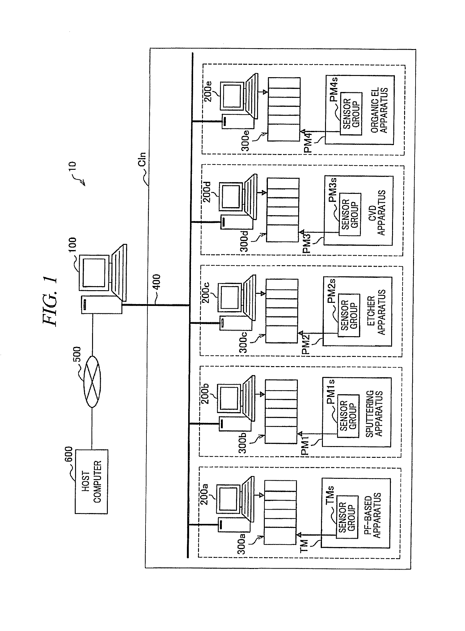
[0056]A substrate processing system in accordance with a first embodiment of the present invention will be explained with reference to FIG. 1. FIG. 1 is a schematic configuration view of the substrate processing system in accordance with the first embodiment.

[0057][Substrate Processing System]

[0058]A substrate processing system 10 may include a main PC (Personal Computer) 100, sub PCs 200a to 200e, safety PLCs (Programmable Logic Controller) 300a to 300e, a transfer module TM, and process modules PM1 to PM4. These devices may be connected with each other via a network 400 such as Ethernet (registered trademark). Further, the main PC 100 may be connected with a host computer 600 via a LAN (Local Area Network) 500.

[0059]The sub PCs 200a to 200e may be respectively positioned in the vicinity of the transfer module TM and the process modules PM1 to PM4 within a clean room Cln. The main PC 100 may be positioned outside the clean room Cln. The main PC 100 may remotely control each of the ...

second embodiment

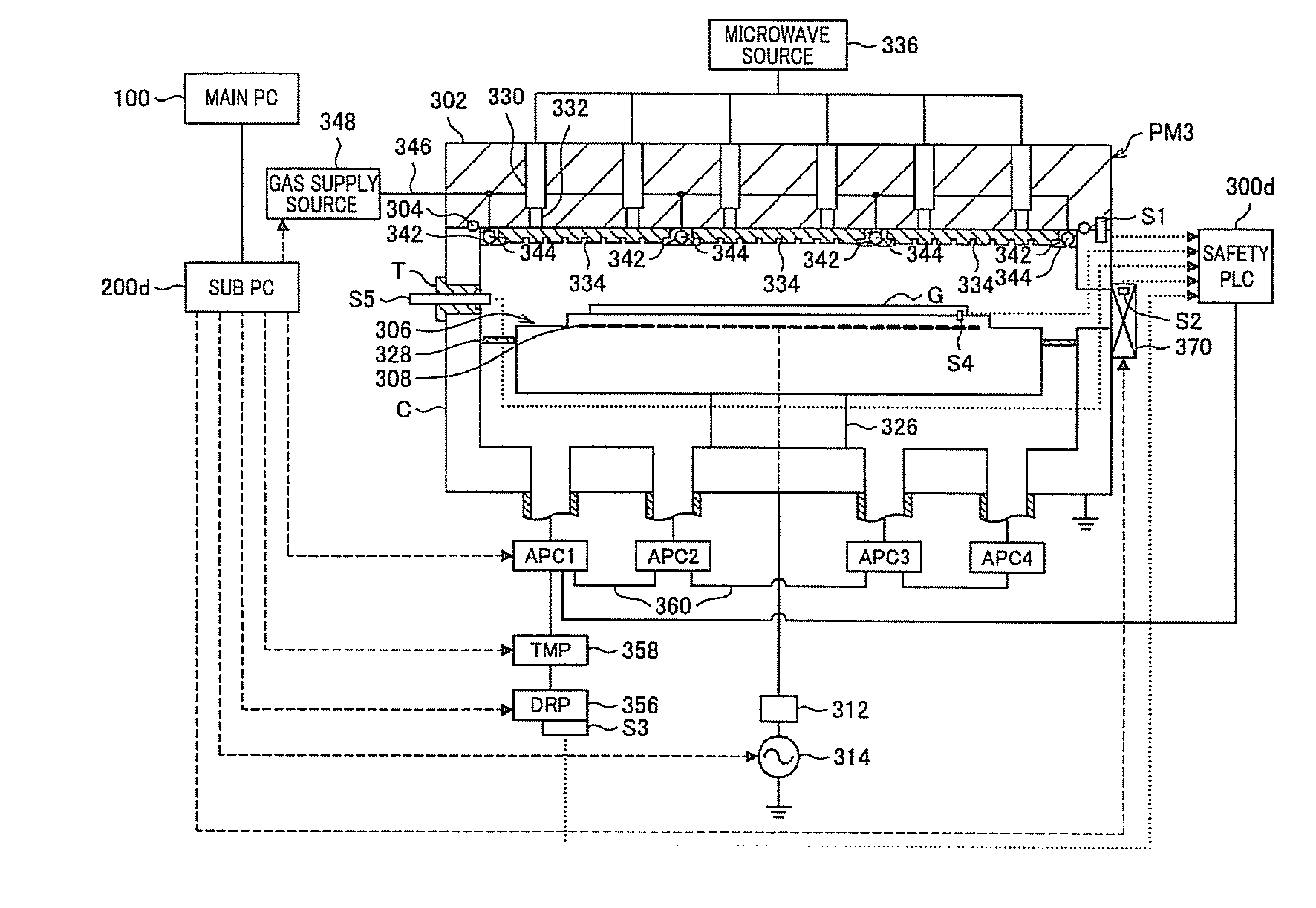
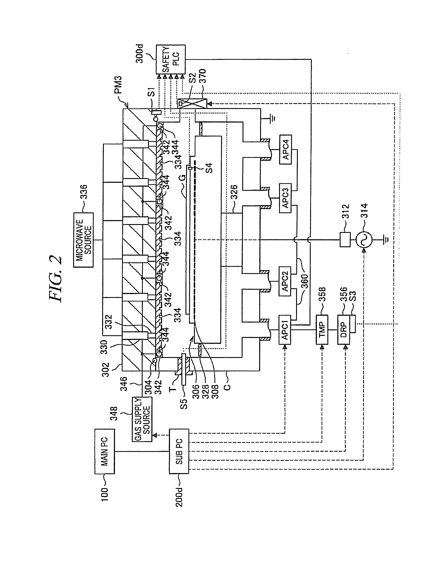
[0123]In the first embodiment, there has been explained an interlock control when an APC valve is used as an evacuation device. The APC valve may be a pressure control valve having a function of a shut-off valve and the APC valve may include the shut-off valve and the pressure control valve as a single part. FIG. 14 is a schematic diagram of a process module when a shut-off valve and a pressure control valve are provided as a single part (in case of an APC valve). FIG. 15 shows an example of an interlock signal input when a shut-off valve and a pressure control valve are provided as a single part (in case of an APC valve). FIG. 16 shows another example of an interlock signal input when a shut-off valve and a pressure control valve are provided as a single part (in case of an APC valve).

[0124]As depicted in FIG. 14, a pressure gauge 705 may detect an internal pressure of the chamber frequently and output a monitored pressure value. The chamber C (processing chamber) may control an op...


PUM

PropertyMeasurementUnit
Pressureaaaaaaaaaa
Electric potential / voltageaaaaaaaaaa
Pressureaaaaaaaaaa

Abstract

A substrate processing system includes a controller that outputs a control signal for controlling a substrate processing apparatus; and a software interlock component that outputs an interlock signal if a predetermined interlock condition is satisfied. In the substrate processing apparatus, a multiple number of devices of the same kind are provided and each device is selected to be either an interlocked state or a non-interlocked state with other devices. The software interlock component outputs an interlock signal to any one of the multiple number of devices of the same kind if it is determined that the multiple number of devices satisfy the predetermined interlock condition. If any one of the multiple number of devices of the same kind receives the interlock signal, the multiple number of devices are interlocked according to an instruction of the interlock signal regardless of an interlocked state or a non-interlocked state of the devices.

Description

TECHNICAL FIELD[0001]The present invention relates to a substrate processing system including an interlock component, a substrate processing method and a storage medium storing a program for implementing a function of the substrate processing system.BACKGROUND ART[0002]Recently, a substrate processing system having a multiple number of cluster substrate processing apparatuses has been provided in a semiconductor manufacturing factory. Each substrate processing apparatus is connected with a controller via a network. The controller outputs a control signal to the substrate processing apparatus at a predetermined time according to a recipe. The substrate processing apparatus controls, for example, opening / closing of various valves and an opening degree of an APC (Automatic Pressure Control) valve or a pump in response to the control signal, so that a process such as an etching process or a film forming process is performed onto a substrate.[0003]When the substrate processing apparatus ...

Claims


Application Information

Patent Timeline
IPC IPC(8): G05B19/418F16K99/00
CPCC23C14/12C23C14/22C23C14/24H01L21/67276C23C16/52C23C16/54C23C16/44H01L21/00G05B19/05G06F9/32
Inventor NISHIMURA, MASARUTAKANO, HIROYUKINISHIJIMA, SOUICHI
Owner TOKYO ELECTRON LTD
Why Eureka
Try Eureka