
Discontinuous Reception in Carrier Aggregation Wireless Communication Systems

Active Publication Date: 2011-11-03
BEIJING XIAOMI MOBILE SOFTWARE CO LTD
View PDF1 Cites 84 Cited by
  • Summary
  • Abstract
  • Description
  • Claims
  • Application Information

AI Technical Summary

Benefits of technology

[0015]According to a further embodiment, an on-duration timer is configured only on the primary component carrier, e.g. by respective signaling of the network element to the user equipment. The on-duration indicating the time duration the user equipment monitors the PDCCH for allocations. According to a further embodiment the offsets of the on-duration are configured by radio resource control (RRC) signaling. Thus the power consumption can be decreased.

Problems solved by technology

On the other hand, besides higher peak data rates, power consumption is an important issue.

Method used


Image

  • Discontinuous Reception in Carrier Aggregation Wireless Communication Systems
  • Discontinuous Reception in Carrier Aggregation Wireless Communication Systems
  • Discontinuous Reception in Carrier Aggregation Wireless Communication Systems

Examples


case 1

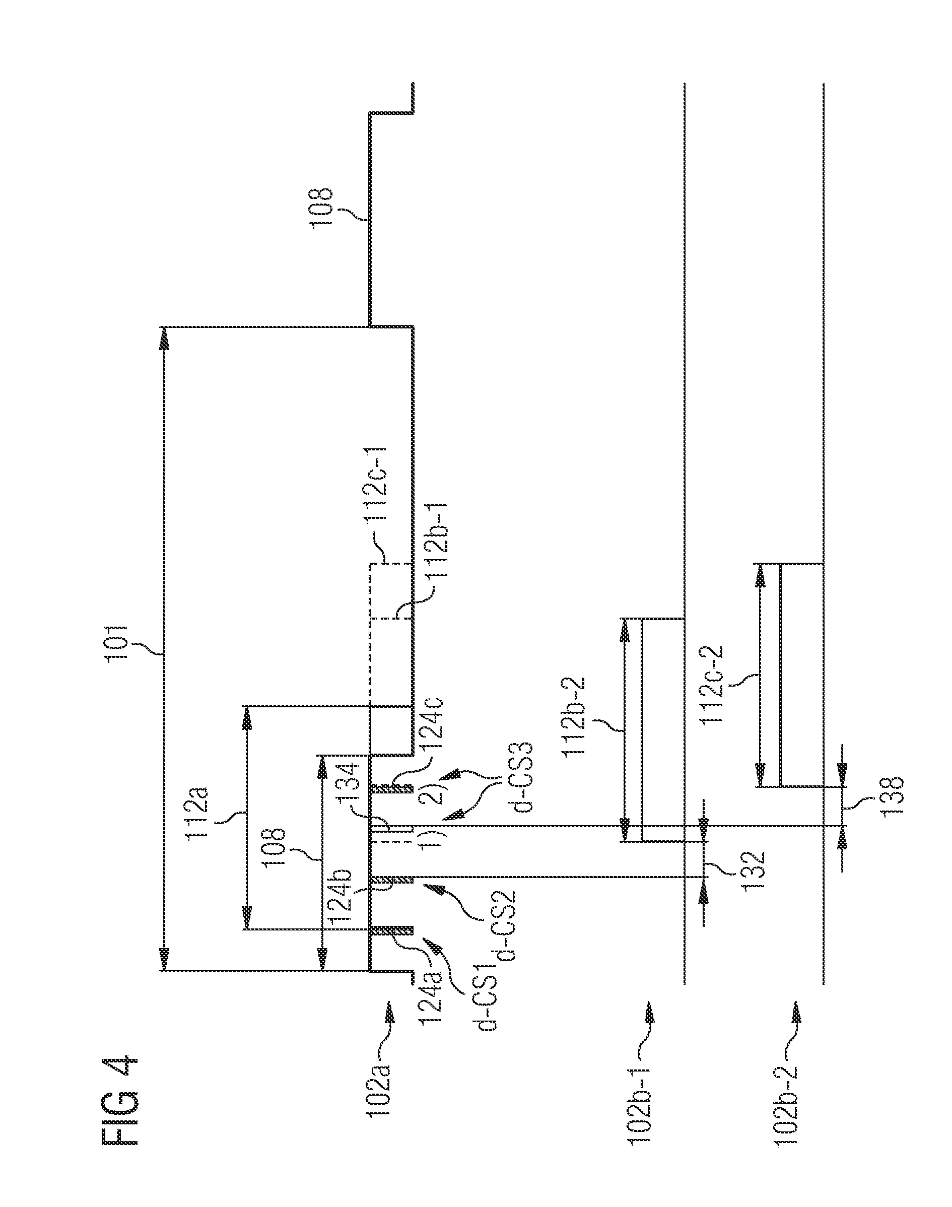
[0093] If a new transmission happens on primary component carrier then the following steps are performed:[0094]Step 1: for eNB, new transmission indication is sent in primary component carrier's PDCCH 124a, indicating the transmission on primary component carrier 102a; and[0095]Step 2: for UE, during active-time on primary component carrier 102a, if a PDCCH indication for primary component carrier is received, DRX inactivity timer is started on primary component carrier in the same subframe. In FIG. 4, the active-time on primary component carrier is not explicitly indicated, but given by the time duration where at least one of the on-duration timer 108 and the inactivity timer 112a is active (respective high levels in FIG. 4).

[0096]According to illustrative embodiments of case 1, indicated at d-CS1 in FIG. 4, if a new transmission happens at primary component carrier 102a, then DRX inactivity timer is started in the same subframe.

case 2

[0097] If a new transmission happens on a first secondary component carrier 102b-1 then the following steps are performed:[0098]Step 1: For eNB, a new transmission indication is sent in primary component carrier's PDCCH 124b, indicating the transmission on secondary component carrier 102b-1;[0099]Step 2: for UE, during active-time on primary component carrier 102a, if a PDCCH 124b indication for secondary component carrier 102b-1 is received, a timing gap 132 is used until the reception on secondary component carrier 1 is available (according to an embodiment shown in FIG. 4, the timing gap 132 is between PDCCH indication and data transmission);[0100]Step 3: DRX inactivity timer 112b-1, 112b-2 is started or restarted on both primary component carrier 102a and secondary component carrier 102b-1, respectively.

[0101]According to illustrative embodiments of case 2, indicated at d-CS2 in FIG. 4, if a new transmission happens at the first secondary component carrier 102b-1, then a timing ...

case 3

[0102] If a new transmission happens on a second secondary component carrier 102b-2 then the following steps are performed:[0103]Step 1: for eNB, a MAC CE or RRC message 134 (i.e. a MAC control element) is sent on primary component carrier 102a indicating signal reception on secondary component carrier 102b-2;[0104]Step 2: for eNB, new transmission indication 124c is sent in primary component carrier's PDCCH, indicating transmission on secondary component carrier 102b-2, after a timing gap 138 (i.e. according to an illustrative embodiment, the timing gap 138 extends between the message indicating signal reception on secondary component carrier 102b-2 and the PDCCH indication);[0105]Step 3: for UE, during active-time on primary component carrier 102a, if a PDCCH indication 124c for a secondary component carrier 102b-2 is received, a DRX inactivity timer 112c-1, 112c-2 is started or restarted on both primary and secondary component carriers 102a, 102b-2.

[0106]According to illustrative...


PUM


Abstract

A communication system is presented, which is capable of sending a transmission over an interface having at least two aggregated component carriers including a primary component carrier and at least one secondary component carrier, wherein the primary component carrier has a physical downlink control channel (PDCCH) associated therewith and wherein the PDCCH is capable of signaling allocations for the primary component carrier and the at least one secondary component carrier. A method of operating a network element including sending to a user equipment a transmission indication indicative of the transmission in the PDCCH of the primary component carrier. A method of operating a user equipment includes monitoring downlink control signaling for a transmission indication indicative of a transmission to the user equipment only on the PDCCH of the primary component carrier.

Description

FIELD OF INVENTION[0001]The present invention relates to the field of wireless communication and in particular to the field of carrier aggregation in wireless communication.ART BACKGROUND[0002]In order to achieve higher peak data rates, it has been proposed operate in spectrum allocations of different sizes including wider spectrum allocations than e.g. those of Release 8 LTE (LTE=Long Term Evolution), e.g. up to 100 MHz, e.g. to achieve the peak data rate of 100 Mbit / s for high mobility and 1 Gbit / s for low mobility. Moreover, backward compatibility is desirable.[0003]A possible measure for achieving wider spectrum allocations is carrier aggregation, where two or more component carriers are aggregated, as it is considered for LTE-Advanced in order to support downlink transmission bandwidths larger than 20 MHz.[0004]A user equipment (UE), e.g. a terminal, may simultaneously receive one or multiple component carriers depending on its capabilities:[0005]An LTE-Advanced terminal with r...

Claims


Application Information

Patent Timeline
IPC IPC(8): H04W52/02H04W24/00H04W72/04H04W76/28
CPCH04L5/0007H04L5/001H04L5/003H04W76/048H04L27/0006H04W72/042H04L5/0053H04W76/28H04W72/23
Inventor DU, LEIHUANG, MINTENG, YONG
Owner BEIJING XIAOMI MOBILE SOFTWARE CO LTD
Learn More