Collimation lens having freeform surface and design method thereof

a collimation lens and freeform surface technology, applied in the direction of instruments, computing, electric digital data processing, etc., can solve the problems of poor optic performance and precision of the optic structure designed in this way, time-consuming and uneconomical, and cannot fit the application of the regular optical structure or the optic assembly, so as to reduce the amount of space occupied, shorten the overall length, and eliminate the trouble of positioning lenses

Inactive Publication Date: 2011-11-03
NATIONAL CHANGHUA UNIVERSITY OF EDUCATION
View PDF0 Cites 47 Cited by
  • Summary
  • Abstract
  • Description
  • Claims
  • Application Information

AI Technical Summary

Benefits of technology

[0022]As such, through practice of the above discussed technical solution according to the present invention, a collimation lens that is constructed according to the present invention is applicable to an LED based light source and overcome the drawbacks of wasting space and poor collimation performance found in the conventional collimation lens systems that are often comp

Problems solved by technology

Consequently, the LED is not fit for applications in regular optical structures or optic assemblies; rather it is more suitable for optic arrangements in respect of collimated light sources.
However, the geometric characteristics of these regular curved surfaces are simple and are of certain limitations, so that in performing designs, several different curved surfaces must be simultaneously used, and further subjected to proper assembling and adjustment, in order to realize the desired optic property.
Such an adjustment process is usually a trial-and-error process, which requires repeated trials and numerous corrections to be done before a satisfactory optic structure is obtained.
This is time consuming and is not economic.
Further, an optic structure designed in this way is poor in both optic performance and precision.
This increases the costs and requires light beam to be

Method used


Image

  • Collimation lens having freeform surface and design method thereof
  • Collimation lens having freeform surface and design method thereof
  • Collimation lens having freeform surface and design method thereof

Examples


Embodiment Construction

[0042]The following descriptions are exemplary embodiments only, and are not intended to limit the scope, applicability or configuration of the invention in any way. Rather, the following description provides a convenient illustration for implementing exemplary embodiments of the invention. Various changes to the described embodiments may be made in the function and arrangement of the elements described without departing from the scope of the invention as set forth in the appended claims.

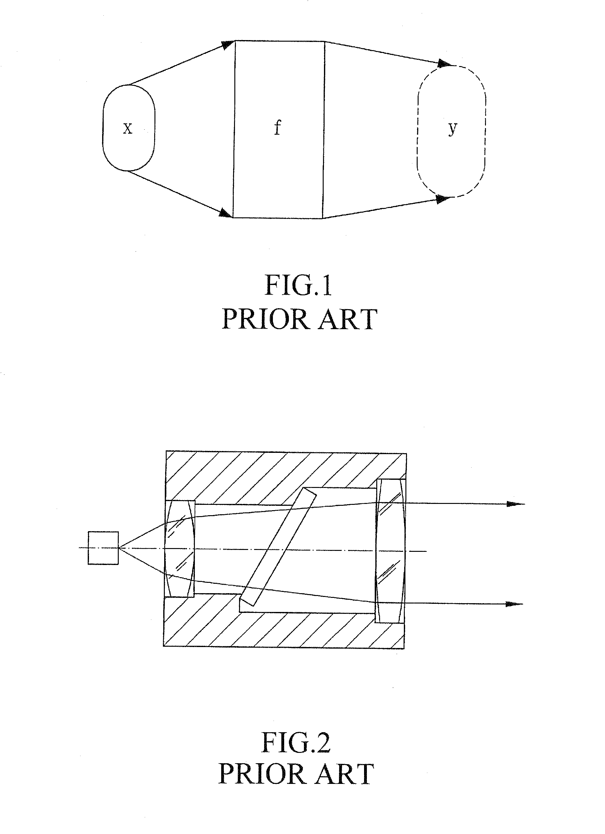
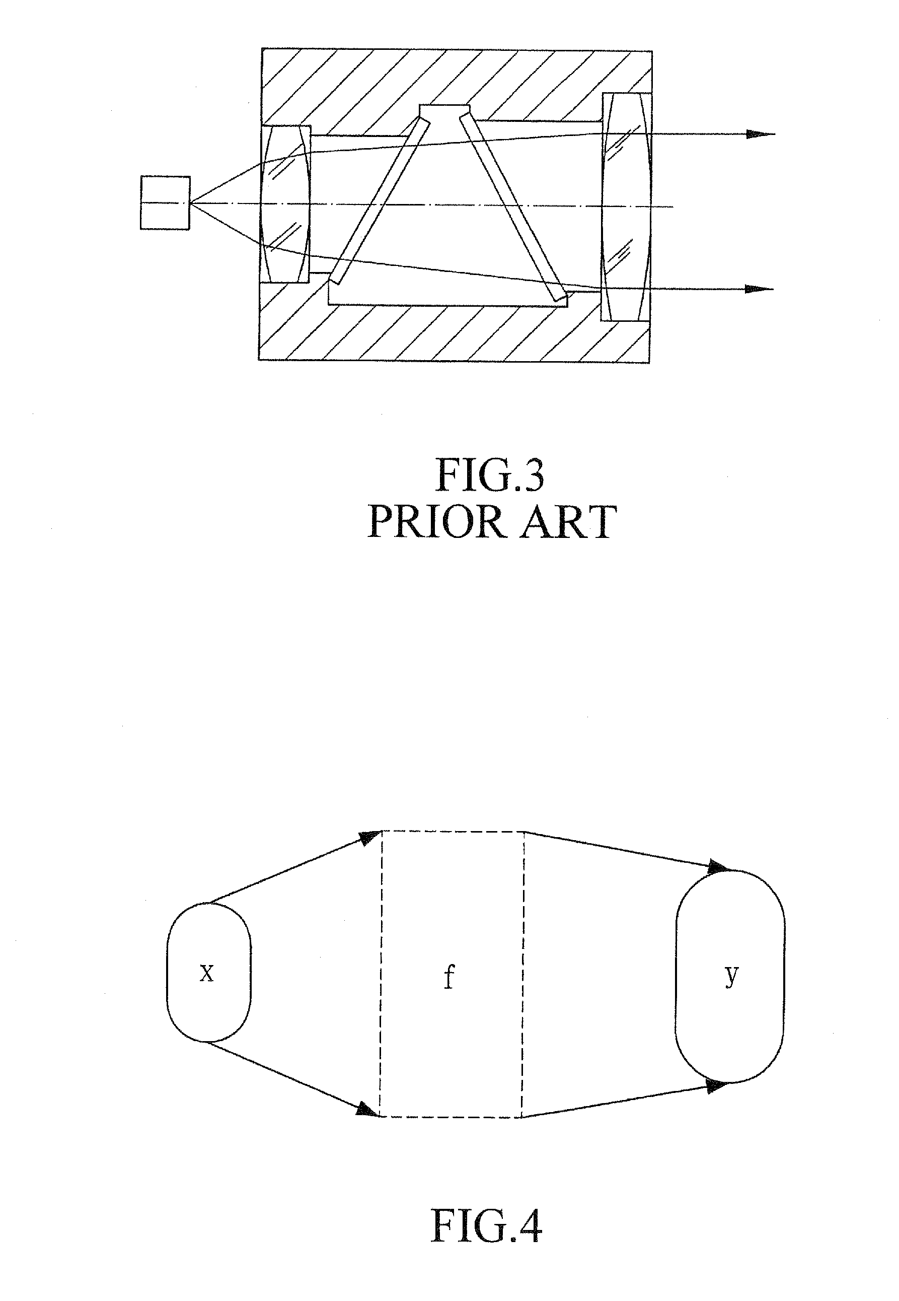
[0043]Referring to FIG. 4, a description will be given, in which “x” indicates an optic field pattern of a light source, “y” indicates an optic field pattern of a receiving surface, and “f” is a function of the optic structure to be designed according to the present invention, whereby the optic system is represented by the formula y=f(x). According to the present invention, an optic structure of a collimation lens is designed with a freeform surface method and thus, known parameters of the design me...


PUM


Abstract

A freeform surface included collimation lens is provided, which is designed through a freeform surface design process to provide an integrally-formed unitary structure. The design method includes a step of identifying an optic field pattern of light source, a step of performing graphic analysis of freeform surface tangential vector formula, a step of acquiring freeform surface control point, a step of constructing a three-dimensional model, and a step of performing geometric processing. Through these steps, tangential vectors of control points of each freeform surface are determined and an approximating process or an exact solution process is adopted to determine the coordinates of the points of the freeform surface. Three-dimensional modeling software is then employing to construct an ellipsoid collimation lens, which realizes an optic collimation performance of at least 88% when tested with a circular disk set at a distance of 200 meters and having a diameter of 35 meters.

Description

TECHNICAL FIELD OF THE INVENTION[0001]The present invention generally relates to the field of design of LED (Light-Emitting Diode) optical collimation lens, and more particularly to the design of integrally-formed collimation lens by adopting freeform surface method in order to shorten the time needed for assembling and adjusting lenses, improve collimation performance, and substantially reduce the amount of space occupied.DESCRIPTION OF THE PRIOR ART[0002]Techniques associated with light-emitting diodes (LED) have been recently under fast development and progress. The LEDs, which were only used for indication purposes, are increasingly replacing various light sources to play an important role as light sources for various lighting systems. Literatures that discuss the applications of LED in various lighting system, such as backlighting, head and ail lights of automobiles, homogeneous lighting systems, and street lighting, are easily available. The LED, which possesses various advant...

Claims


Application Information

Patent Timeline
IPC IPC(8): G06F17/50G02B27/30
CPCG02B27/30G02B3/02
Inventor CHEN, JIN-JIALIN, CHIN-TANG
Owner NATIONAL CHANGHUA UNIVERSITY OF EDUCATION
Why Eureka
Try Eureka