Laminated smd-type thermistors and manufacturing methods thereof

Inactive Publication Date: 2011-11-10
SHANGHAI KETER POLYMER MATERIAL
View PDF5 Cites 3 Cited by
  • Summary
  • Abstract
  • Description
  • Claims
  • Application Information

AI Technical Summary

Benefits of technology

[0010]Aspects of the present invention generally pertain to provide a laminated SMD-type thermistor and manufacturing method thereof, the laminated SMD-type thermistor has a superior performance and a high rate of qualified products, its manufacturing method has a unique process, no etching, a greatly reduced cost, a sable process, a high accuracy and a high yield rate, and is environmentally-friendly.

Problems solved by technology

However, the current laminated SMD-type thermistors with PTC property have some defects both in design and manufacturing, and the structure designs and the manufacturing processes of the prior laminated SMD-type thermistors with PTC property will be illuminated hereinafter.
But the chemical etching method has inherent shortcomings in technologies, firstly, the etching solution used in the process has a severe pollution to the environment, and also has relatively great harm to human bodies and mechanical equipments; secondly, the open accuracy of the process is relatively low, thus the rate of finished products is relatively low; thirdly, it is easy for the subsequent procedure after the etching process to make the etching pattern produce abnormal phenomena such as shift, dislocation and so on, making the process unstable.
In addition, in the structures of various SMD-type thermistors with PTC property published previously, the etching areas are formed by etching on the upper and lower surfaces of the metal foil, thus affecting its effective usable area, and when it is welded to the circuit board, it is possible that the welding position deviation may cause short-circuit.
(1) There are too many materials (resistance chip with PTC property, metal foil, plating resistant film, insulating film, surface metal layer, etc.) required in forming the element, which makes the total cost of the raw materials relatively high;
(2) For there are too many materials, the procedure required is complicated, making the total rate of finished products relatively low;
(3) For there are too many materials, when the processes such as heat processing and so on are performed, it is easy for the pattern layer to produce abnormal phenomena such as shift, dislocation and so on, thus making the process unstable.

Method used


Image

  • Laminated smd-type thermistors and manufacturing methods thereof
  • Laminated smd-type thermistors and manufacturing methods thereof
  • Laminated smd-type thermistors and manufacturing methods thereof

Examples


embodiment 1

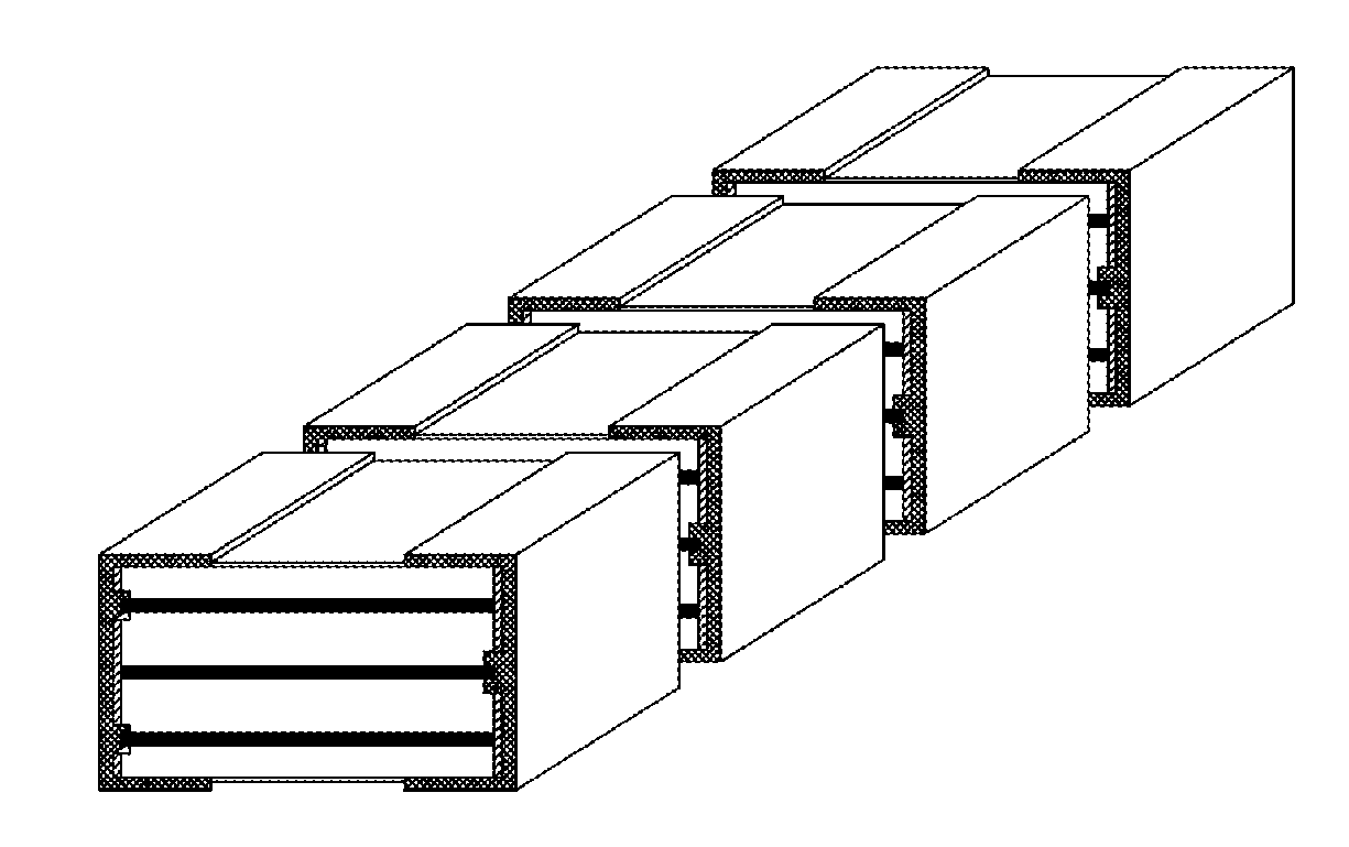
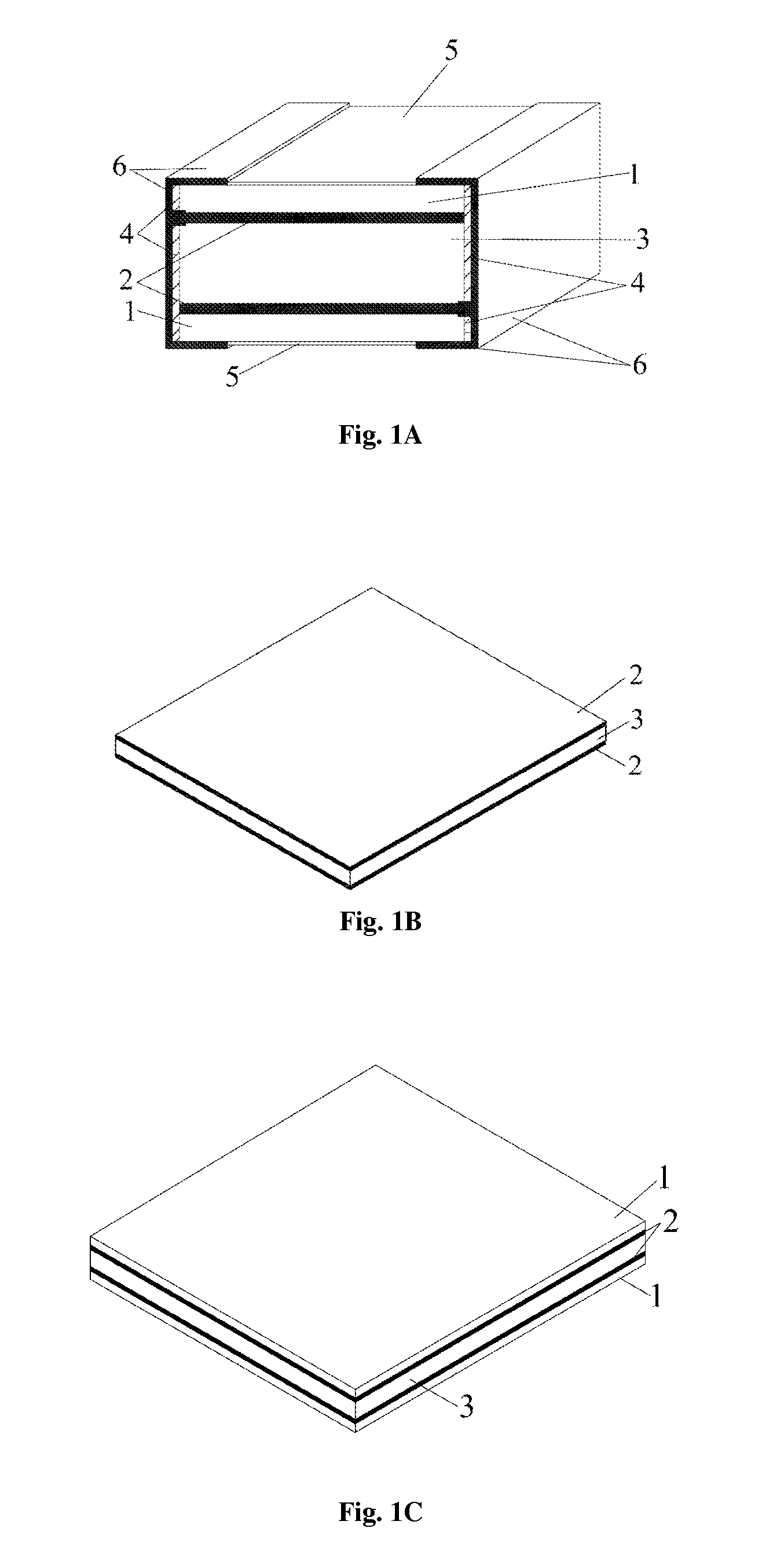
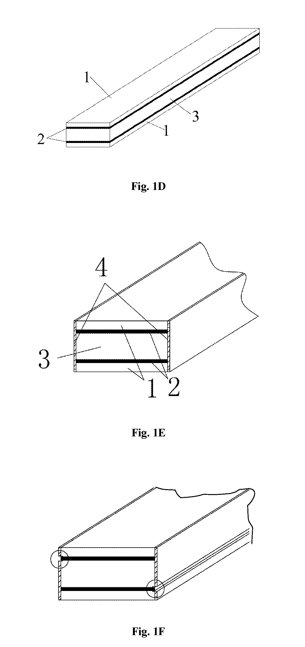
[0108]The laminated SMD-type thermistor with PTC property and manufacturing method thereof of Embodiment 1 of the present invention are exemplified by reference to FIG. 1A˜FIG. 1I.

[0109]FIG. 1A is the structure view of the laminated SMD-type thermistor with PTC property of Embodiment 1 of the present invention.

[0110]In FIG. 1A, the conductive polymer chip 3 with PTC property is a macromolecular polymer sheet formed by a mixture including one or more crystalline polymers, conductive fillers, processing aids and so on, the metal foils 2 are coated evenly on the upper and lower surfaces of the above-mentioned conductive polymer chip 3 with PTC property; the insulating films 1 are coated tightly and evenly on the surfaces of the above-mentioned two metal foils 2; the insulating glue 4 is applied on the left and right sides of the above-mentioned conductive polymer chip 3 with PTC property, the insulating glue 4 on the two sides is divided into four parts totally; the plating resistant f...

embodiment 2

[0122]The laminated SMD-type thermistor with PTC property and manufacturing method thereof of Embodiment 2 of the present invention are exemplified by reference to FIG. 2A˜FIG. 2D.

[0123]FIG. 2A is the structure view of the laminated SMD-type thermistor with PTC property of Embodiment 2 of the present invention.

[0124]In FIG. 2A, the conductive polymer chip 3 with PTC property is a macromolecular polymer sheet formed by a mixture including one or more crystalline polymers, conductive fillers, processing aids and so on, the metal foils 2 are coated evenly on the upper and lower surfaces of the above-mentioned conductive polymer chip 3 with PTC property; the insulating films 1 are coated tightly and evenly on the surfaces of the above-mentioned two metal foils 2; the insulating glue 4 is applied on the left and right sides of the above-mentioned conductive polymer chip 3 with PTC property, the insulating glue 4 on the two sides is divided into four parts totally; one physical processing...

embodiment 3

[0129]The laminated SMD-type thermistor with PTC property and manufacturing method thereof of Embodiment 3 of the present invention are exemplified by reference to FIG. 3A˜FIG. 3E.

[0130]FIG. 3A is the structure view of the laminated SMD-type thermistor with PTC property of Embodiment 3 of the present invention.

[0131]In FIG. 3A, the conductive polymer chip 3 with PTC property is a macromolecular polymer sheet formed by a mixture including one or more crystalline polymers, conductive fillers, processing aids and so on, the metal foils 2 are coated evenly on the upper and lower surfaces of the above-mentioned conductive polymer chip 3 with PTC property; the insulating films 1 are coated tightly and evenly on the surfaces of the above-mentioned two metal foils 2, the insulating films 1 on the two metal foils 2 are divided into four parts totally; the insulating glue 4 is applied on the left and right sides of the above-mentioned conductive polymer chip 3 with PTC property; the plating r...


PUM

PropertyMeasurementUnit
Electrical resistanceaaaaaaaaaa
Shapeaaaaaaaaaa
Electrical conductoraaaaaaaaaa

Abstract

A laminated SMD-type thermistor has a conductive module, a left and a right conductive metal layer. The conductive module includes a core conductive module coated with an insulating layer on the upper and lower surface, and the left and right side. The core conductive module includes at least one conductive unit piled up in sequence, two conductive units are separated by an insulating material layer. The conductive unit includes an upper metal foil, a conductive polymer chip and a lower metal foil which are laminated in sequence from top to bottom. A left and right conductive metal layer are coated on the left and right part of the conductive module respectively, and penetrate the insulating layer partially, to connect with two metal foils of the conductive unit respectively. The laminated SMD-type thermistor can further comprise two plating resistant films coated on the upper and lower surface of the conductive module.

Description

FIELD OF TECHNOLOGY[0001]The present invention relates to the field of thermistors, more particularly, to the field of SMD (Surface Mounted Device)-type thermistors, especially, to laminated SMD-type thermistors and manufacturing methods thereof.DESCRIPTION OF RELATED ARTS[0002]Thermistors with positive temperature coefficient (PTC) property have been used widely in the circuit protection of the field of 6C industries such as computers, communications, consumer electronics, cars, closed circuits, digital contents and so on. Their working principle is that: when the circuit works properly, the value R0 of the PTC thermistor is very small and does not hinder the passage of the current; and when the circuit has failures such as overcurrent, overload or overheat, the surface temperature of the thermistor rises rapidly, when it rises over the switch temperature, the thermistor rises to a high impedance state instantly, so as to limit the circuit current timely to a very low level to prot...

Claims


Application Information

Patent Timeline
IPC IPC(8): H01C7/13H01C7/02
CPCH01C1/1406H01C1/148Y10T29/49085H01C7/18H01C7/027
Inventor HUANG, JINHUAWANG, PENGXINGGONG, QINGGUOSHI, YUZHENGLIAO, JIANGQUAN
Owner SHANGHAI KETER POLYMER MATERIAL
Why Eureka
Try Eureka