Electric blower and electric vacuum cleaner utilizing the same

Inactive Publication Date: 2011-11-17
PANASONIC CORP
View PDF2 Cites 13 Cited by
  • Summary
  • Abstract
  • Description
  • Claims
  • Application Information

AI Technical Summary

Benefits of technology

[0014]With the configuration, in the inside of the flow passage of the air guide, the flow velocity distribution of the air is made uniform t

Problems solved by technology

For this reason, there has been a problem that suct

Method used


Image

  • Electric blower and electric vacuum cleaner utilizing the same
  • Electric blower and electric vacuum cleaner utilizing the same
  • Electric blower and electric vacuum cleaner utilizing the same

Examples


Example

First Exemplary Embodiment

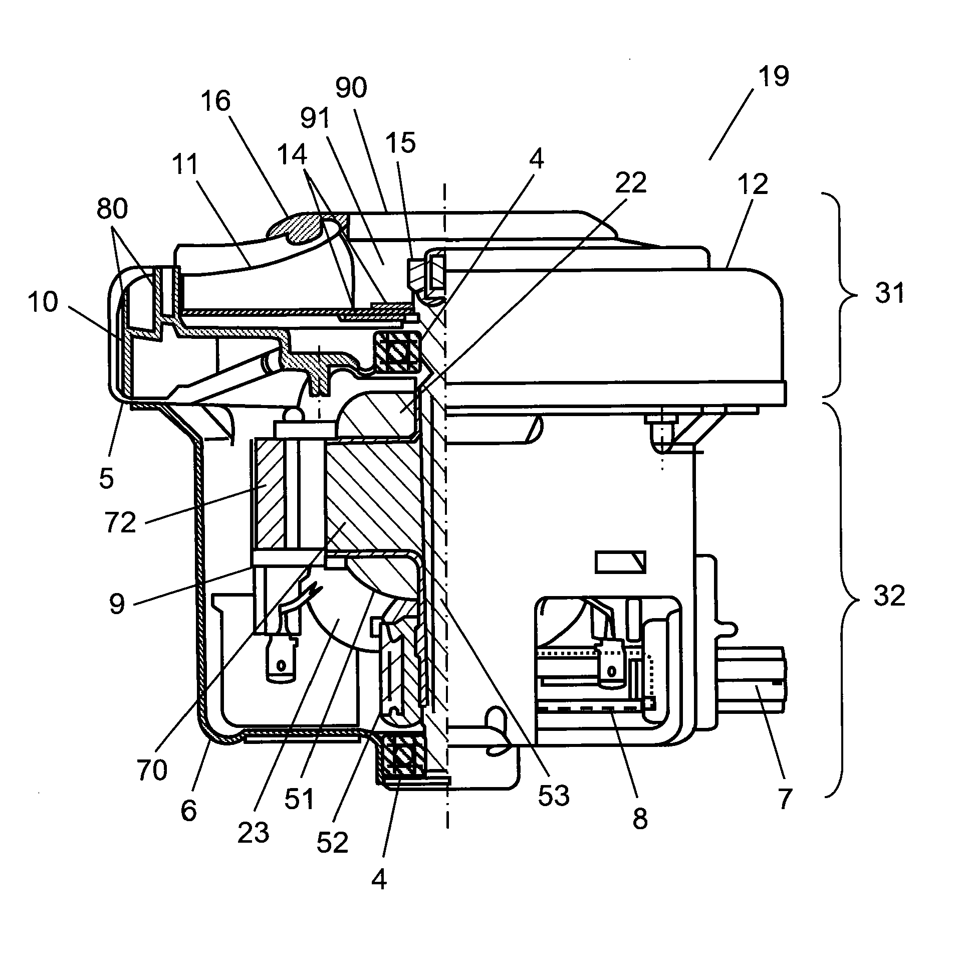
[0027]FIG. 1 is a partial cross-sectional view of a lateral side of an electric blower according to a first embodiment of the present invention. As shown in FIG. 1, electric blower 19 includes motor section 32 and fan section 31.

[0028]Motor section 32 includes armature 51 that has shaft 53, armature core 70, and commutator 52. At an outer periphery of armature core 70, armature coil 22 is wound. In addition, motor section 32 includes magnetic field system 9 in which magnetic field winding 23 is wound at an outer periphery of magnetic field core 72. On both ends of shaft 53 of armature 51, axle-bearings 4 are press fitted. One of axle-bearings 4 is supported by anti-load side bracket 6. Moreover, motor section 32 includes brush holder 7 made of a metal, which houses carbon brush 8.

[0029]Fan section 31 includes: impeller 11 that sucks in air, i.e. a load, and blows out the sucked air as well, casing 12 that covers over impeller 11, load side bracket 5, and ai...

Example

Second Exemplary Embodiment

[0037]FIG. 4 is a cross-sectional view of around an impeller and an air guide of an electric blower according to a second embodiment of the invention. The embodiment is different from the first embodiment in terms of shapes of: base portion 84; flow passage bottom face 80c of flow passage 81; inner wall-surface 80b of guide vane 80 on the outer peripheral side; and a coupling portion of flow passage bottom face 80c with inner wall-surface 80b of guide vane 80 on the outer peripheral side, of the first embodiment. The other constitutions are the same as those of the first embodiment. The same constitutional elements are designated by the same numerals and symbols, and a detailed explanation thereof is omitted.

[0038]As shown in FIG. 4, flow passage bottom face 80c of air guide 10 according to the embodiment is a horizontal and flat face. Note that the horizontal and flat face is a face perpendicular to shaft 53. In accordance with the shape of flow passage b...

Example

Third Exemplary Embodiment

[0040]FIG. 5 is a cross-sectional view of around an impeller and an air guide of an electric blower according to a third embodiment of the invention. The embodiment is different from the second embodiment in terms of a shape of the coupling portion of flow passage bottom face 80c with inner wall-surface 80b of guide vane 80 on the outer peripheral side of the second embodiment. The other constitutions are the same as those of the second embodiment. The same constitutional elements are designated by the same numerals and symbols, and a detailed explanation thereof is omitted.

[0041]As shown in FIG. 5, in air guide 10 according to the embodiment, the coupling portion of flow passage bottom face 80c with inner wall-surface 80b of guide vane 80 on the outer peripheral side, has a circular arc shape having radius R. Radius R is equal to a width of flow passage 81.

[0042]With this configuration, length B of a straight-line portion in the shaft 53 direction of inner...


PUM


Abstract

Air guide (10) that rectifies air blown out from an impeller includes a plurality of guide vanes (80) having a circular arc shape. In a cross-sectional shape of each one of flow passages (81) of air guide (10), length B of a straight-line portion in a shaft direction of an inner wall-surface formed by one of guide vanes (80) on an outer peripheral side is small compared with length A of a straight-line portion in a shaft direction of an inner wall-surface formed by one of guide vanes (80) on an inner peripheral side. This provides a uniformed flow velocity distribution inside flow passages (81), resulting in a reduced loss caused by differences in flow velocity.

Description

TECHNICAL FIELD[0001]The present invention relates to an electric blower and a vacuum cleaner using thereof.BACKGROUND ART[0002]As a conventional electric blower, the electric blower disclosed in Patent Literature 1 is known, for example. FIG. 8 is a partially-cutaway cross-sectional view of the electric blower described in Patent Literature 1. Electric blower 119 includes motor section 132 and fan section 131.[0003]Motor section 132 includes: armature 151 having shaft 153, armature core 170, and commutator 152. At an outer periphery of armature core 170, armature coil 122 is wound. In addition, motor section 132 includes magnetic field system 109 in which magnetic field winding 123 is wound at an outer periphery of magnetic field core 172. On both ends of shaft 153 of armature 151, axle-bearings 104 are press fitted. One of axle-bearings 104 is supported by anti-load side bracket 106. Moreover, motor section 132 includes brush holder 107 made of a metal, which houses carbon brush 1...

Claims


Application Information

Patent Timeline
IPC IPC(8): B08B5/04F04B35/04
CPCF04D29/281F04D29/665F04D29/444F05D2250/52
Inventor NAKAMURA, KAZUSHIGEMORISHITA, KAZUHISAHIDEKUMA, TEPPEIKAYAMA, HIROYUKINISHIMURA, TSUYOSHI
Owner PANASONIC CORP
Why Eureka
Try Eureka