
Restoration Anchoring System

a technology of anchoring system and cavity wall, which is applied in the direction of shock absorption, covering/lining, building repairs, etc., can solve the problems of masonry veneer cracking and spalling, affecting the economics of manufacture, and requiring remediation of the instability of the cavity wall, etc., and achieves the effect of low unit cost and economics of manufactur

Active Publication Date: 2011-11-17
HOHMANN & BARNARD INC
View PDF13 Cites 56 Cited by
  • Summary
  • Abstract
  • Description
  • Claims
  • Application Information

AI Technical Summary

Benefits of technology

[0027]It is another object of the present invention to provide labor-saving devices to aid in remedial anchoring of seismic-type installations of brick and stone veneer and the securement thereof to an inner wythe.
[0028]It is a yet another object of the present invention to provide a restoration anchoring system comprising a limited number of component parts that are economical of manufacture resulting in a relatively low unit cost.
[0031]It is a further feature of the present invention that the restoration anchoring system hereof restricts lateral and horizontal movements of the facing wythe with respect to the inner wythe.

Problems solved by technology

From time-to-time or with the passage of time, cavity walls have been known to experience levels of instability requiring remediation.
Instability may result from any of a number of causes, namely, inter alia: including improper installation of the original anchoring system; the corrosion of imbedded reinforcing steel, a seismic event; settlement of the building, unanticipated differences in thermal expansion; and, historic high-wind shear conditions.
Such instability results in masonry veneer cracking and spalling, the most frequent cause of masonry performance failure and potentially dangerous to the building occupants and pedestrians.
Among these options typically complete removal of a veneer and subsequent replacement is impractical and expensive.
Similarly, the partial removal of sections or stories of veneer is unsafe and costly.
The remediation of a failed structure is in many ways more difficult than forming the original construct.
While the Ollis helical dowel serves to reconnect the veneer to the inner wythe, it fails to provide a connection to a reinforcement wire that is set within the horizontal bed joint to form a seismic construct.

Method used


Image

  • Restoration Anchoring System
  • Restoration Anchoring System
  • Restoration Anchoring System

Examples


first embodiment

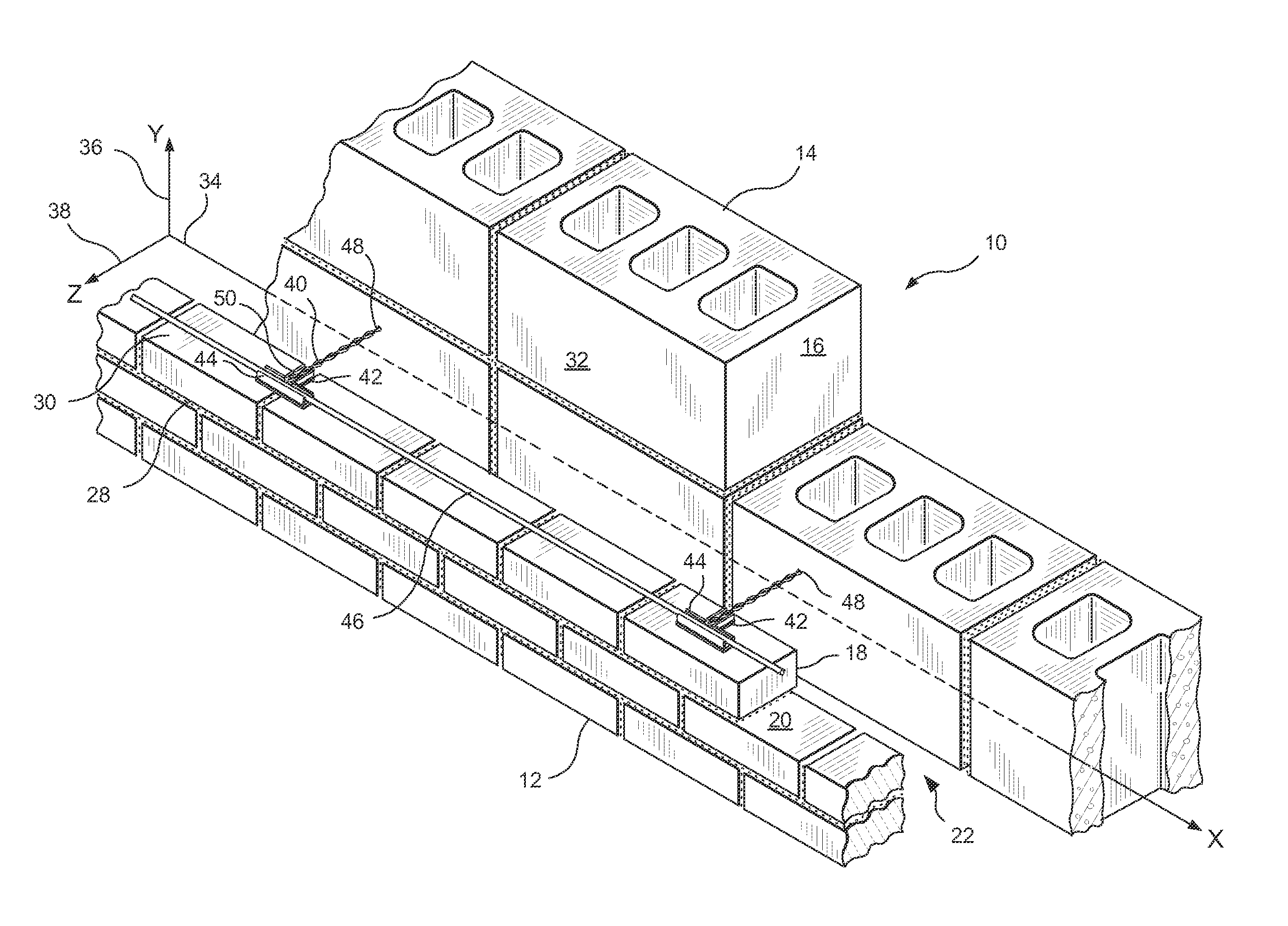
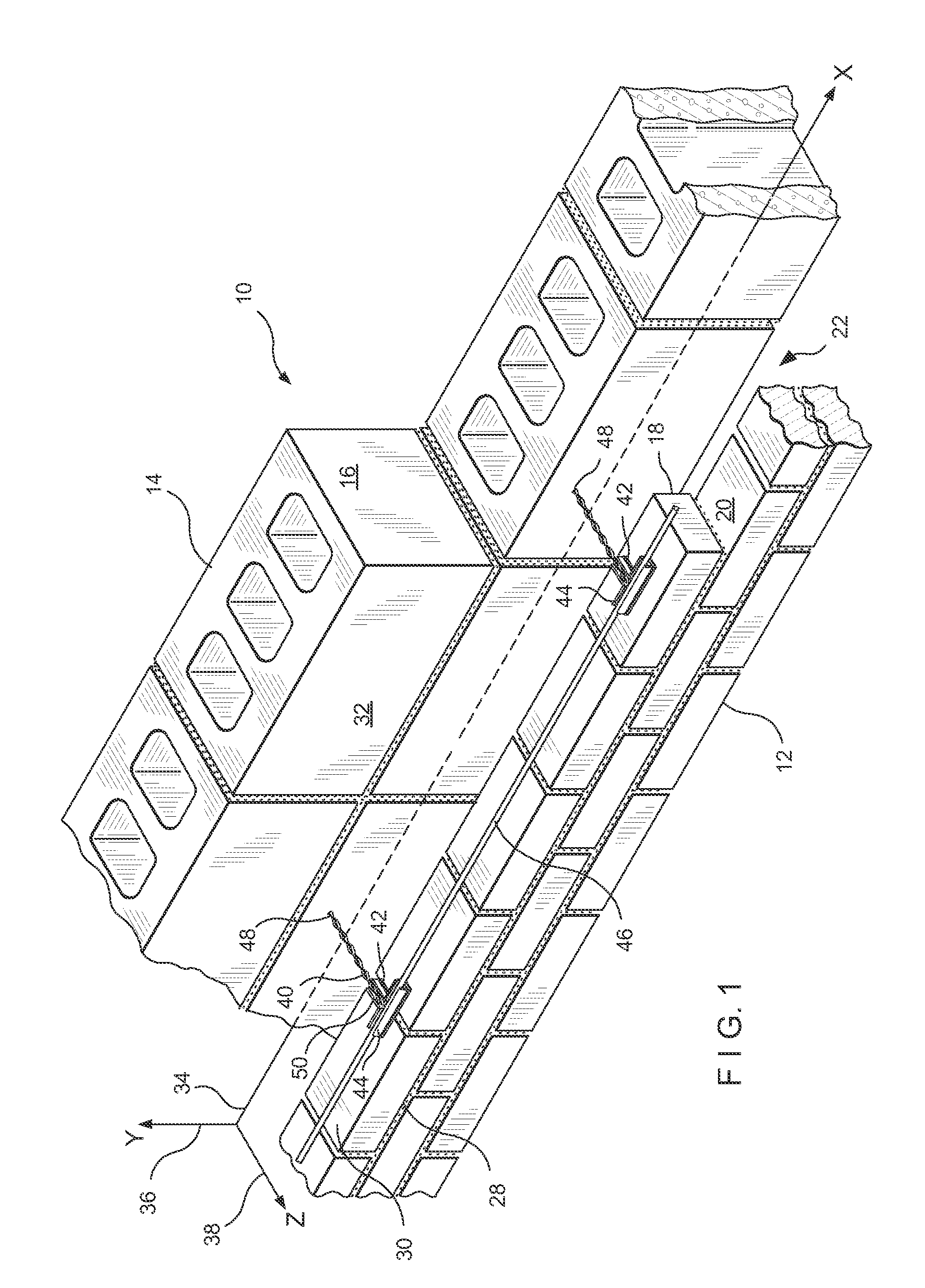
[0049]Referring now to FIGS. 1 through 8, a restoration seismic anchoring system of this invention is shown as applied to an existing cavity wall. The construct is referred to generally by the numeral 10. In this embodiment, a wall structure 12 is shown having an interior wythe 14 of masonry blocks 16 and an exterior wythe 18 of facing brick 20. Between the interior wythe 14 and the exterior wythe 18, a cavity 22 is formed.

[0050]In the first embodiment, successive bed joints 28 and 30 are formed between courses of bricks 20 and the joints are substantially planar and horizontally disposed. For purposes of discussion, the exterior surface 32 of the interior wythe 14 contains a horizontal line or x-axis 34 and an intersecting vertical line or y-axis 36. A horizontal line or z-axis 38 also passes through the coordinate origin formed by the intersecting x- and y-axes.

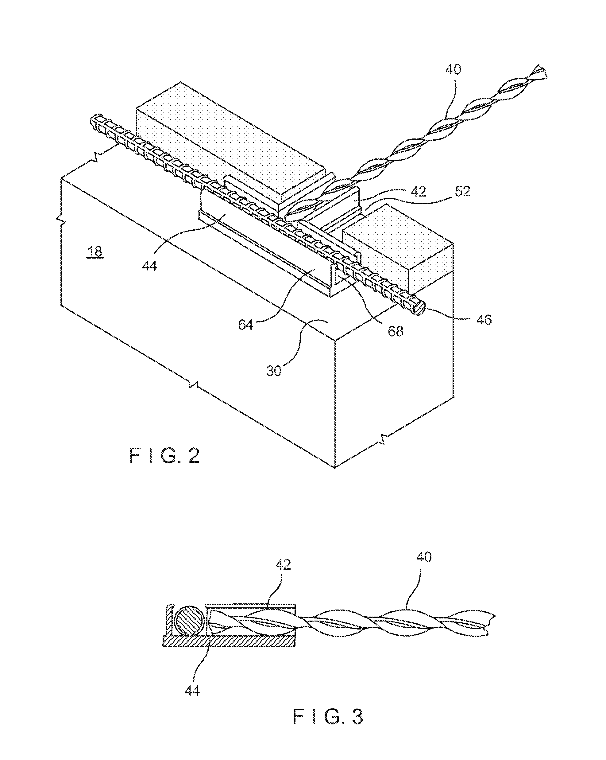
[0051]The present invention contains three components, namely, the helical dowel 40, the seismic T-clip 44 and the reinfo...

second embodiment

[0057]In the second embodiment, successive bed joints 128 and 130 are formed between courses of bricks 120 and the joints are substantially planar and horizontally disposed. For purposes of discussion, the exterior surface 132 of the interior wythe 114 contains a horizontal line or x-axis 134 and an intersecting vertical line or y-axis 136. A horizontal line or z-axis 138 also passes through the coordinate origin formed by the intersecting x- and y-axes. The exterior surface of the inner wythe 114 is optionally covered in a sheathing or insulative layer 133.

[0058]The present invention contains three components, namely, the helical dowel 180, the seismic T-clip 44 and the reinforcement member 146. The reinforcement member takes the form of another helical dowel or a wire formative, however, it is anticipated that any similar reinforcement member is within the contemplation of this invention. These restoration anchoring components, when installed within the cavity wall structure, seve...

third embodiment

[0065]In the third embodiment, successive bed joints 228 and 230 are formed between courses of bricks 220 and the joints are substantially planar and horizontally disposed. For purposes of discussion, the exterior surface 232 of the interior wythe 214 contains a horizontal line or x-axis 234 and an intersecting vertical line or y-axis 236. A horizontal line or z-axis 238 also passes through the coordinate origin formed by the intersecting x- and y-axes. The exterior surface of the inner wythe 214 is optionally covered in a sheathing or insulative layer (not shown).

[0066]The present invention contains three components, namely, the helical dowel 292 the seismic T-clip 44 and the reinforcement member 246. The reinforcement member takes the form of another helical dowel or a wire formative, however, it is anticipated that any similar reinforcement member is within the contemplation of this invention. These restoration anchoring components, when installed within the cavity wall structure...


PUM

PropertyMeasurementUnit
heightaaaaaaaaaa
helix angleaaaaaaaaaa
thermoplasticaaaaaaaaaa

Abstract

A restoration anchoring system for use in cavity wall structures having an inner wythe and an outer wythe that requires remediation or re-anchoring is disclosed. The anchoring system employs a three-part system that is installed within the existing bed joints of the outer wythe to reattach and re-anchor the outer wythe to the structural inner wythe. The three-part system includes a helical dowel, a seismic T-clip and a reinforcement member. The helical dowel is self-threading and self-drilling. When the three-part system is installed within the outer wythe and attached to the inner wythe, the system is captively embedded in the outer wythe thereby providing a seismic construct.

Description

BACKGROUND OF THE INVENTION[0001]1. Field of the Invention[0002]This invention relates to a restoration anchoring system for cavity walls, and, more particularly to an anchoring system that remedies the fault that has occurred and constructs a repaired wall that withstands seismic and high-wind load conditions. The anchoring system includes a novel restoration seismic clip.[0003]2. Background of the Prior Art[0004]The construction of cavity walls consisting of an inner wythe or backup wall and an outer wythe or veneer is well known. During construction, the inner and outer portions are tied together by anchoring systems governed by local customs and building codes, which systems are designed to ensure structural integrity and to resist destructive forces.[0005]The inventors' patents and their assignee's product line include masonry accessories, namely, ladder and truss reinforcements, wall anchors, veneer ties, masonry flashing and related items for cavity walls. These products, whi...

Claims


Application Information

Patent Timeline
Patent Type & Authority Applications(United States)
IPC IPC(8): E04B1/21E04C2/20E04B1/98
CPCE04G23/0222
Inventor HOHMANN, JR., RONALD P.
Owner HOHMANN & BARNARD INC
Learn More