Low on-resistance mosfet implemented, by-pass diode or circuit breaker and related self-powering and control circuit

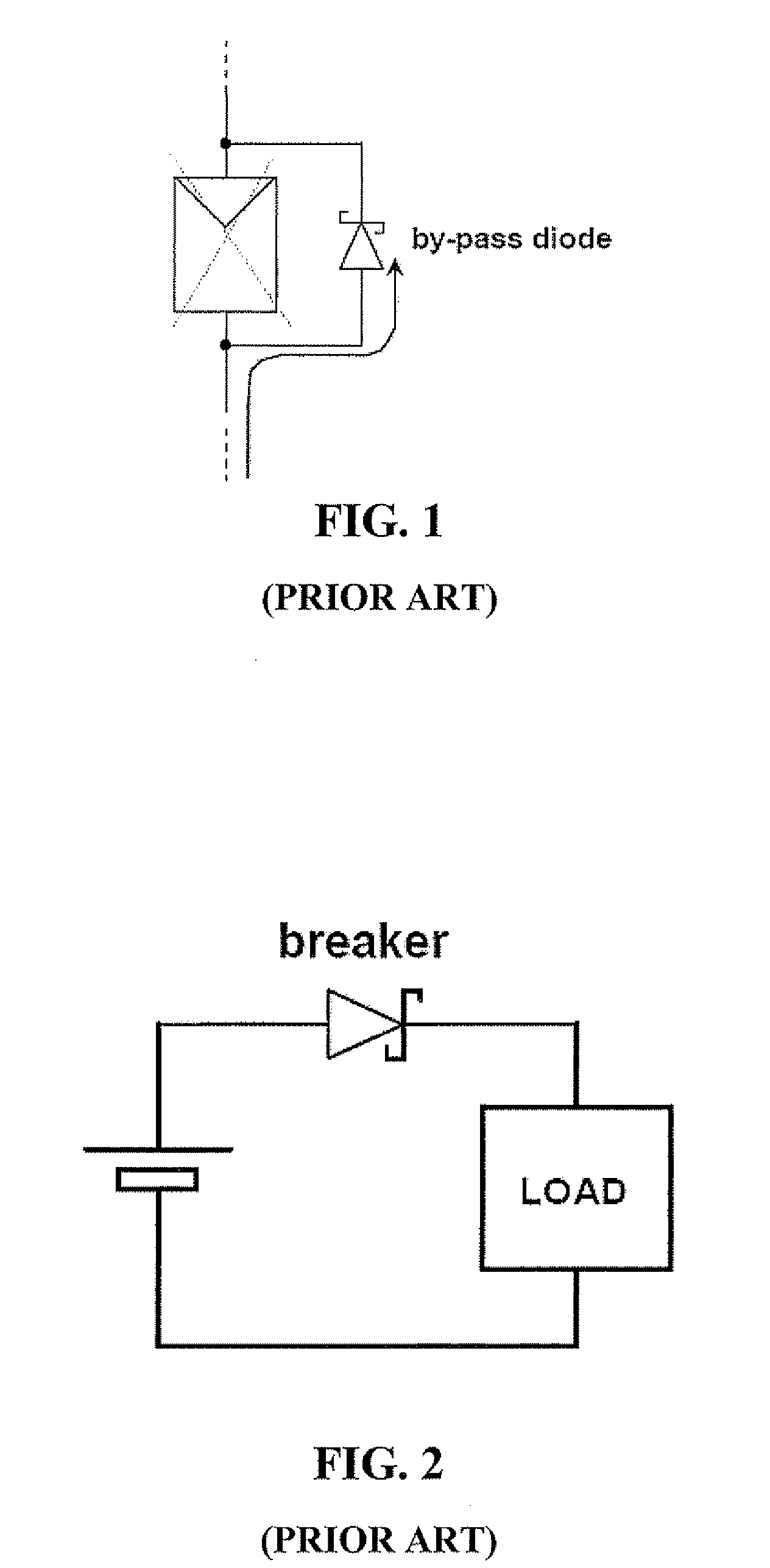
a low-resistance, circuit-breaker technology, applied in the direction of photovoltaic energy generation, dc network circuit arrangement, electrical equipment, etc., can solve the problem of significant power loss in the conducting by-pass diode, the possibility of inadvertent reverse of the supply battery polarity, and the breakdown of the shadowed cells

Active Publication Date: 2011-11-17
STMICROELECTRONICS SRL
View PDF0 Cites 94 Cited by
  • Summary
  • Abstract
  • Description
  • Claims
  • Application Information

AI Technical Summary

Benefits of technology

[0012]It is an object of the invention to provide a more effective current by-pass power diode useful in photovoltaic panel conversion systems or similar DC power distrib...

Problems solved by technology

Momentarily blinded or failed cells do not generate any electricity and are not conductive, thus other series connected illuminated cells may produce a voltage condition across one or several cells of the string that may momentarily be shadowed or practically blinded, which may cause a voltage breakdown and irreversible damage of the shadowed cells.
Moreover, one or more faulty or blinded cells of a string may subtract the contribution to the overall power yield of a large number of other illuminated cells of the panel.
Finally in battery powered systems, it cannot be excluded the possibility that the supply battery polarity be inadvertently reversed.
In these conditions a significantly large power lo...

Method used


Image

  • Low on-resistance mosfet implemented, by-pass diode or circuit breaker and related self-powering and control circuit
  • Low on-resistance mosfet implemented, by-pass diode or circuit breaker and related self-powering and control circuit
  • Low on-resistance mosfet implemented, by-pass diode or circuit breaker and related self-powering and control circuit

Examples


Embodiment Construction

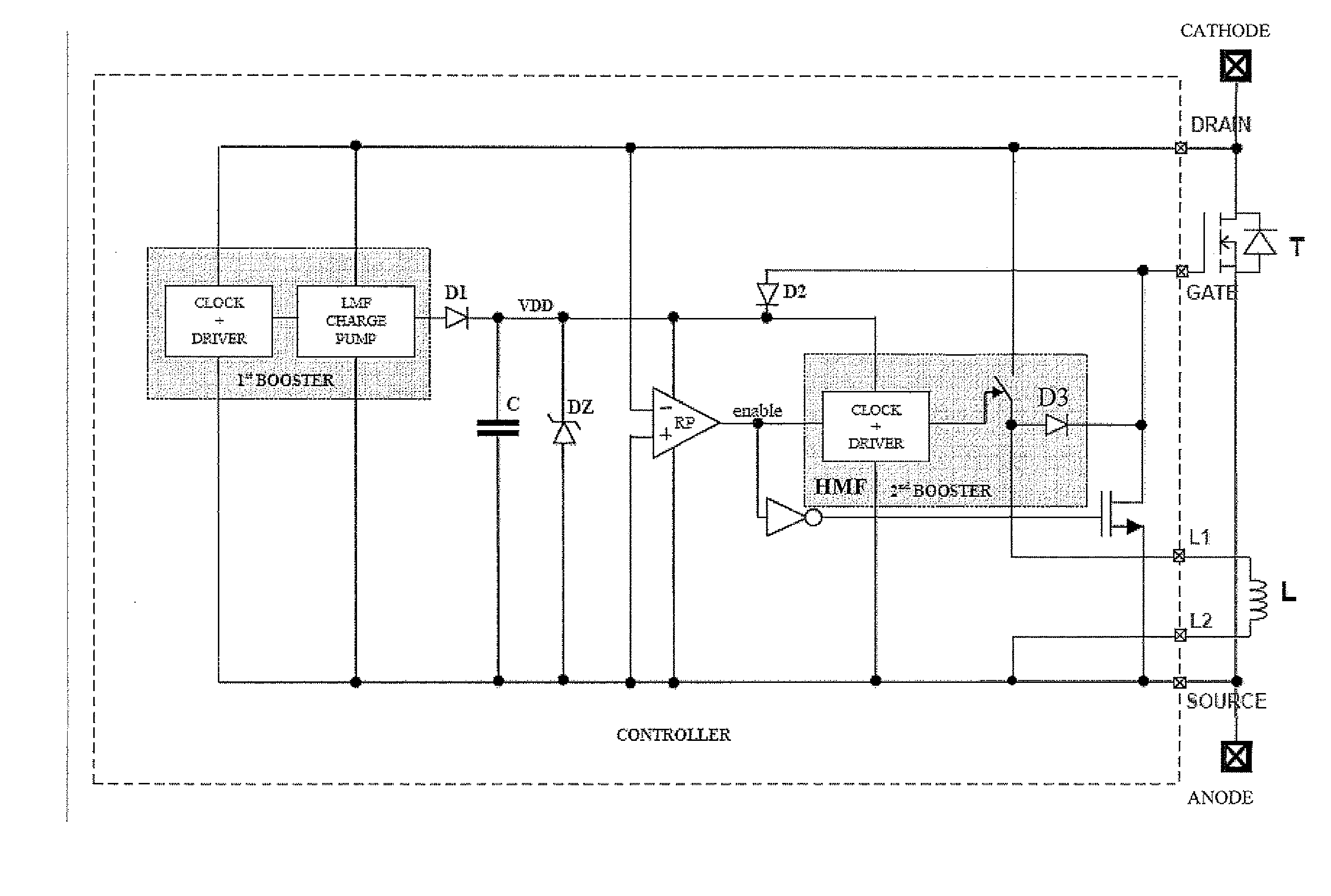
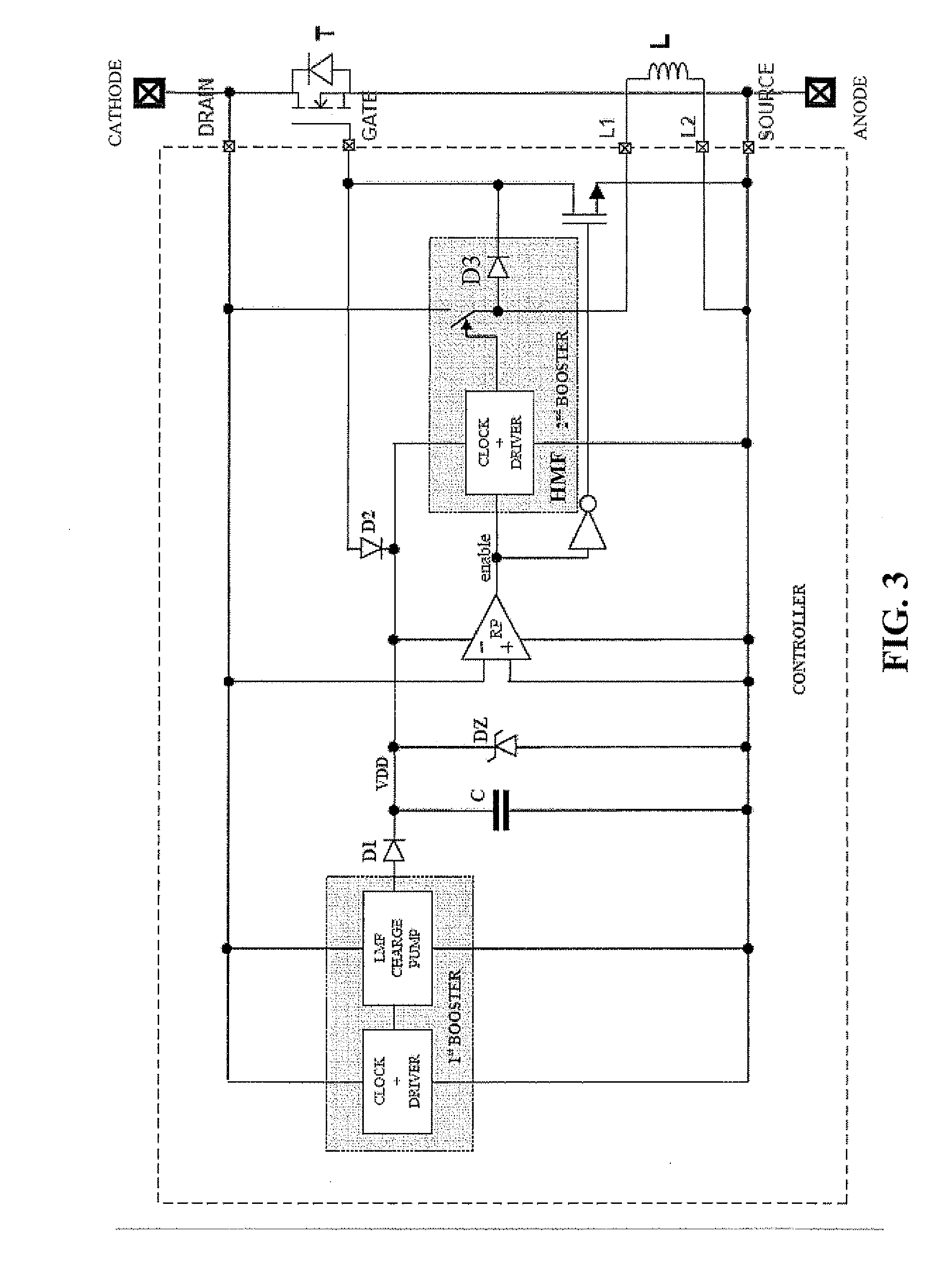
[0021]An exemplary embodiment of the by-pass diode system-in-package device of this disclosure is depicted in FIG. 3. In the illustrated embodiment, the power switching component T is in the form of a discrete N-channel MOSFET power transistor T, the current terminals of which are connected, respectively, to anode and cathode leads of an external connection of the system-in-package device.

[0022]The state of the switching device T is controlled by an integrated control circuit contained inside the broken line perimeter that uses a discrete inductor L connected to the pads L1 and L2 of the integrated circuit to the other connection pads of which connect the source, the drain and the gate of the controlled discrete N-channel MOSFET.

[0023]A start-up voltage booster, 11 commonly including a common drive clock phases generating circuit and driver stage of a low multiplication factor charge pump circuit, that eventually becomes supplied by a negative drain / source voltage difference on the ...


PUM


Abstract

A MOSFET implemented self-powered current by-pass or circuit breaker device is based on the use of a high multiplication factor (HMF) inductive voltage booster, adapted to boost a voltage as low as few tens of mV up to several Volts, assisted by a start-up low multiplication factor (LMF) charge pump made with low threshold transistors for providing a supply voltage to a polarity inversion detecting comparator of the drain-to-source voltage difference of a power MOSFET connected in parallel to a DC source or string of series connected DC sources or battery, in series to other DC sources during normal operation of the parallel connected DC source or string of series connected DC sources or battery. The inductance for the high multiplication factor, inductive voltage booster for most of the considered power applications is on the order of a few pH and such a relatively send inductor may be included as a discrete component in a compact package or “system-in-package” of monolithically integrated circuits.

Description

FIELD OF THE INVENTION[0001]The present invention generally relates to integrated circuits for supplying and controlling a low conduction resistance MOSFET to efficiently function as a by-pass diode or as a safety reverse polarity circuit breaker in a photovoltaic conversion system or similar multiple DC sources power distribution network and battery powered systems.BACKGROUND OF THE INVENTION[0002]In a photovoltaic (PV) conversion system using multicellular solar panels, optimization of power yield under varying conditions of illumination of generally series connected strings of photovoltaic cells, imposes deployment of a way for automatically by-passing strings of series connected cells that are momentarily shadowed or blinded. Momentarily blinded or failed cells do not generate any electricity and are not conductive, thus other series connected illuminated cells may produce a voltage condition across one or several cells of the string that may momentarily be shadowed or practical...

Claims


Application Information

Patent Timeline
IPC IPC(8): H02J1/00
CPCH01L31/02021H02J7/35Y02E10/50H03K17/302H03K17/063
Inventor SIGNORELLI, TIZIANA TERESAPULVIRENTI, FRANCESCO
Owner STMICROELECTRONICS SRL
Why Eureka
Try Eureka