Internal combustion engine

a combustion engine and internal combustion technology, applied in the direction of machines/engines, liquid fuel feeders, mechanical apparatuses, etc., can solve the problems of low rotational speed and considerable torque gain, and achieve the effect of improving combustion, improving mixture preparation, and promoting “knocking” of internal combustion engines

Active Publication Date: 2011-11-24
ROBERT BOSCH GMBH
View PDF7 Cites 6 Cited by
  • Summary
  • Abstract
  • Description
  • Claims
  • Application Information

AI Technical Summary

Benefits of technology

[0003]The internal combustion engine according to an example embodiment of the present invention having the features described herein has the advantage that fuel may be supplied in the direction of the intake valve in different ways, using the two differently configured injectors which inject into the intake port of the at least one combustion cylinder, resulting in greatly improved mixture preparation and combustion in various operating ranges of the internal combustion engine. Thus, for a warm internal combustion engine under high load, it is advantageous to inject the fuel with a high degree of penetration, with the intake valve open, directly into the combustion chamber, while for a cold internal combustion engine a high degree of wetting of the wall region of the intake port immediately upstream from the intake valve results in improved combustion, since the wall film only arrives in the combustion chamber in a time-delayed manner. Using the differing configurations for the two injectors, this operating point-dependent optimization of the combustion may be easily achieved in various operating ranges of the internal combustion engine by controlling the two injectors in different manners. Thus, by using the two injectors in different manners, the lambda distribution in the combustion chamber may be optimized in various operating ranges, a localized overly rich air-fuel ratio associated with high hydrocarbon (HC) concentrations as well as a localized overly lean air-fuel ratio which promotes “knocking” of the internal combustion engine may be avoided, and fuel consumption may be reduced. Thus, in cold start mode, for example, the mixture preparation may be improved and the HC emissions reduced by using the first injector, on account of the smaller fuel droplets in its spray cone. Under full load, as the result of increased use of the second injector, together with the greater penetration all the way to the combustion chamber and minimized wall film generation in the intake port, the heat of evaporation of the fuel is removed more intensely from the cylinder charge than from the wall of the intake port, thus providing greater cooling of the cylinder charge and reducing the sensitivity to knocking.

Problems solved by technology

Scavenging may be achieved with a tolerable load for the catalytic converter, and in conjunction with turbocharging results in a considerable torque gain at low rotational speeds.

Method used


Image

  • Internal combustion engine
  • Internal combustion engine
  • Internal combustion engine

Examples


Embodiment Construction

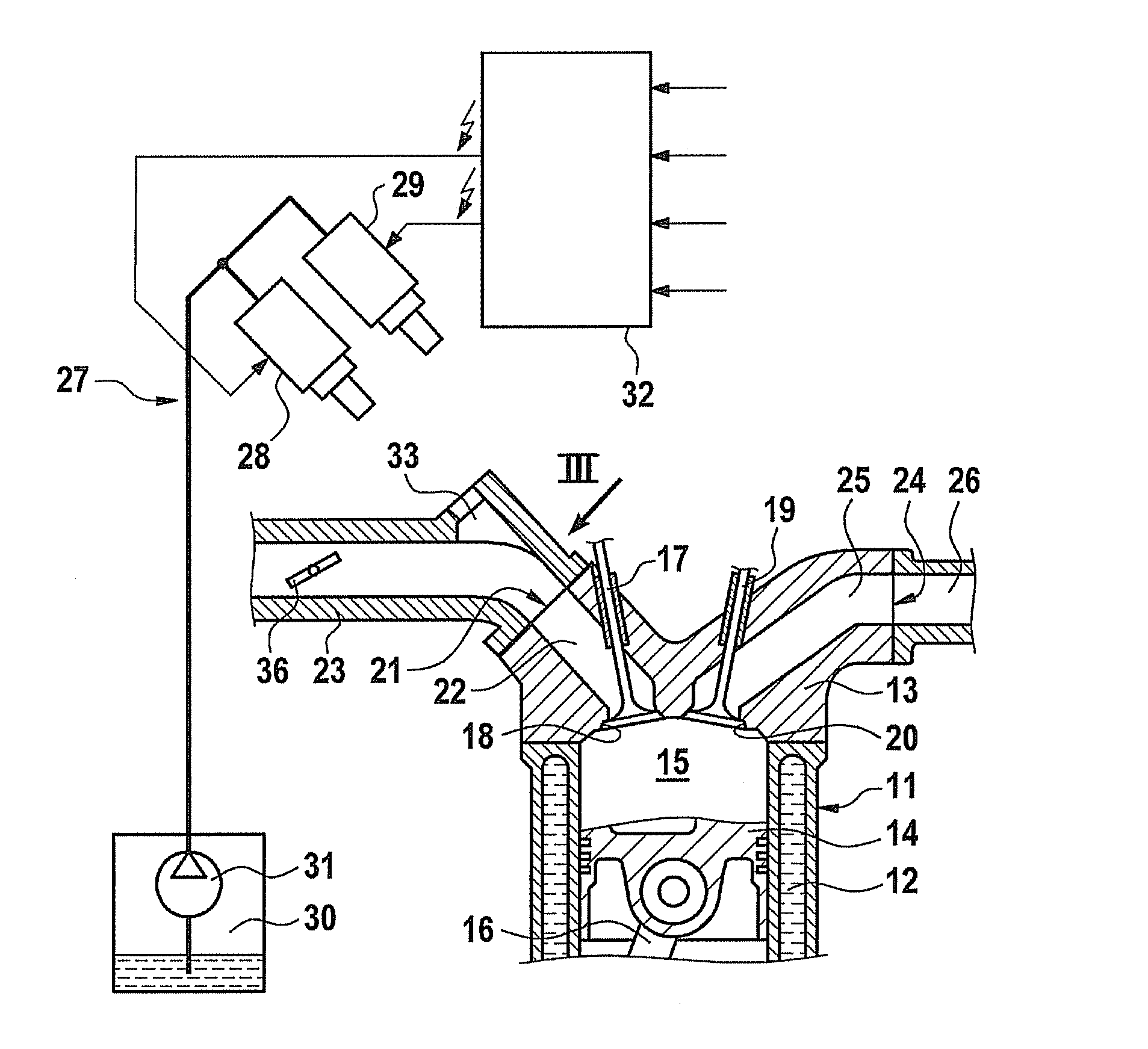
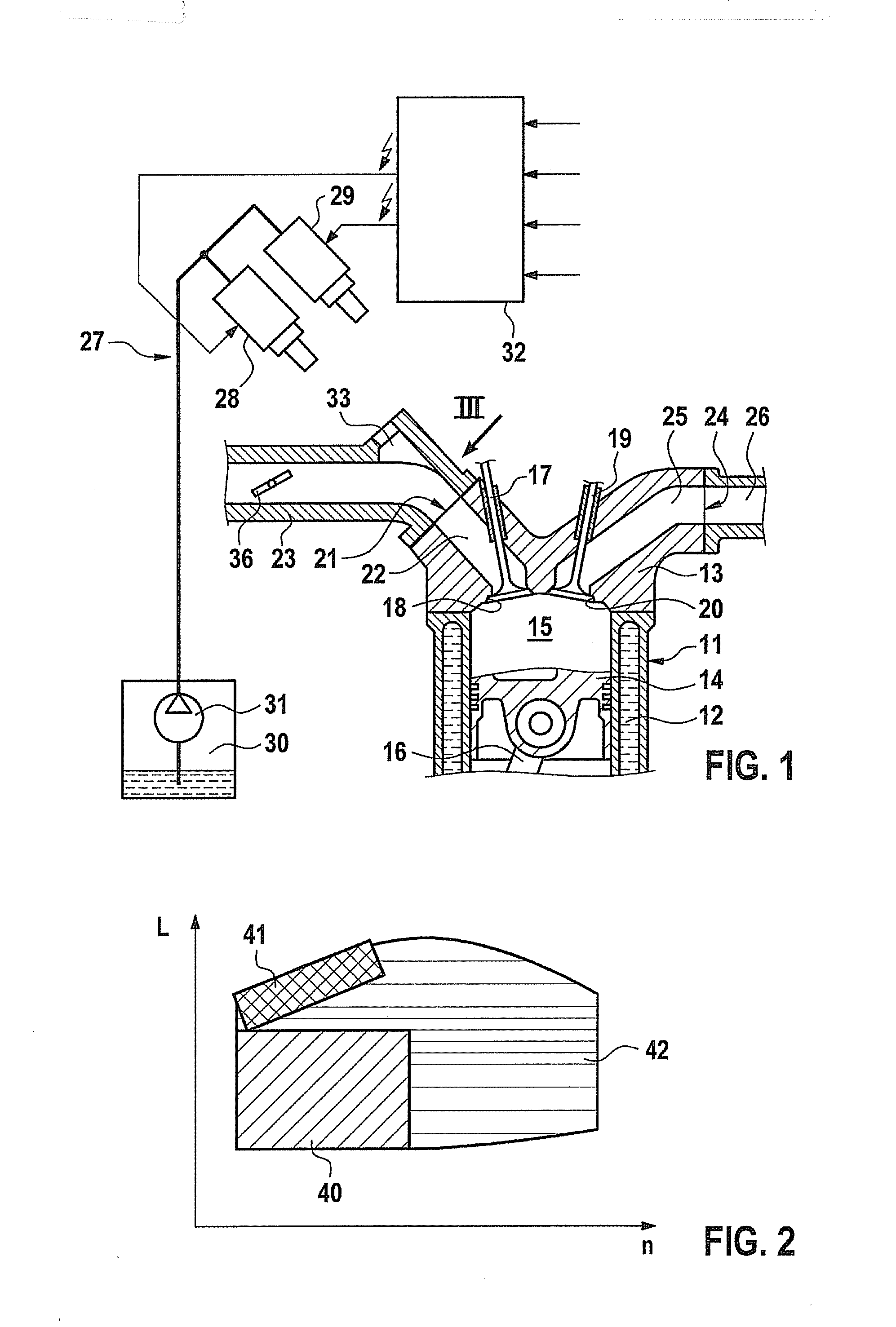
[0017]Of a typically multicylinder internal combustion engine for motor vehicles, for example, only one combustion cylinder 11, shown in a detail in a longitudinal section, is schematically illustrated in FIG. 1. Combustion cylinder 11, which is surrounded on the outside by a cooling water jacket 12, is covered on the end face by a cylinder head 13 in a gas-tight manner. A reciprocating piston 14 which is guided in combustion cylinder 11 in an axially displaceable manner, together with cylinder head 13, delimits a combustion chamber 15. Reciprocating piston 14 is connected via a connecting rod 16 to a crankshaft (not illustrated here), upon which the reciprocating pistons of the other combustion cylinders also act.

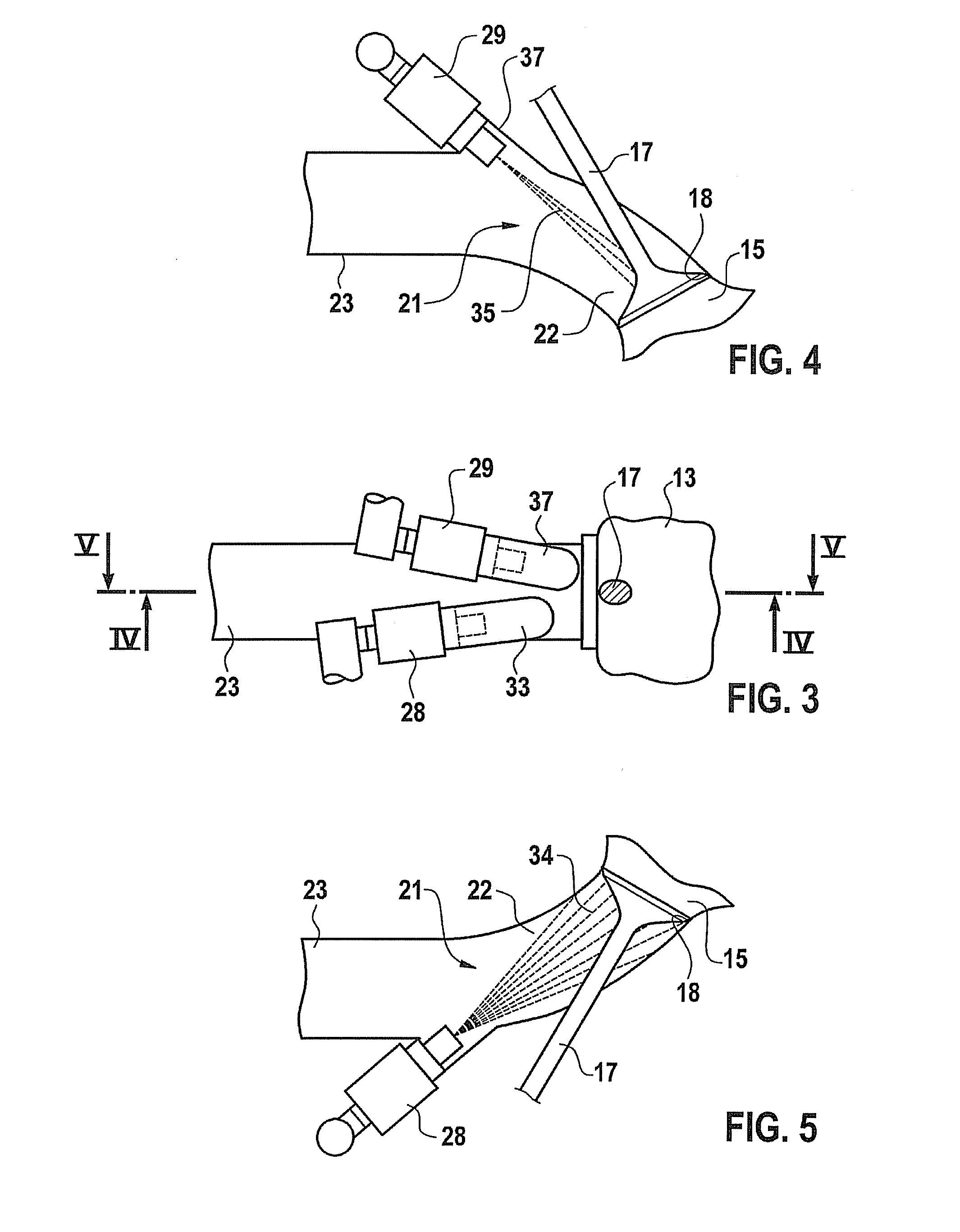
[0018]In a first exemplary embodiment illustrated in FIGS. 3 through 5 in conjunction with FIG. 1, combustion chamber 15 has an inlet 18 which may be closed by an intake valve 17, and an outlet 20 which may be closed by an exhaust valve 19. An intake port 21 for combustion...


PUM


Abstract

An internal combustion engine has at least one combustion chamber which may be closed by an intake valve, at least one air intake port which leads to the intake valve, and a fuel injection device which in association with the at least one combustion chamber has a first injector and a second injector for the metered injection of fuel into at least one intake port. To achieve significantly improved mixture preparation and combustion of the fuel-air mixture in the combustion chamber, the two injectors are configured such that the first injector injects a widely divergent spray cone having a large cone angle, and the second injector injects an only slightly divergent spray cone having a much smaller cone angle.

Description

FIELD OF THE INVENTION[0001]The present invention is directed to an internal combustion engine.BACKGROUND INFORMATION[0002]In one known fuel injection device for an internal combustion engine (JP-10196440 A), the first injector and second injector each inject into the intake port of the internal combustion engine, the first injector injecting upstream from a throttle valve inserted into the intake port for air flow regulation, and the second injector injecting downstream from the throttle valve, the injection by the second injector occurring prior to the injection by the first injector.SUMMARY[0003]The internal combustion engine according to an example embodiment of the present invention having the features described herein has the advantage that fuel may be supplied in the direction of the intake valve in different ways, using the two differently configured injectors which inject into the intake port of the at least one combustion cylinder, resulting in greatly improved mixture pre...

Claims


Application Information

Patent Timeline
Patent Type & Authority Applications(United States)
IPC IPC(8): F02M61/14F02M51/06
CPCF02M69/044F02M69/043F02M63/02
Inventor BAEUERLE, MICHAELSCHWEINSBERG, ALEXANDER SCHENCK ZURIES-MUELLER, KLAUS
Owner ROBERT BOSCH GMBH
Why Eureka
Try Eureka