Passivation methods and apparatus for achieving ultra-low surface recombination velocities for high-efficiency solar cells

a solar cell and ultra-low surface technology, applied in the field of photovoltaics and solar cells, can solve the problems of affecting the production of devices, affecting the efficiency of passivation/arc layer, and affecting the production efficiency of devices, so as to achieve superior surface passivation methods, eliminate or reduce disadvantages and problems, the effect of enhancing optical properties

Inactive Publication Date: 2011-11-24
BEAMREACH SOLAR INC
View PDF12 Cites 44 Cited by
  • Summary
  • Abstract
  • Description
  • Claims
  • Application Information

AI Technical Summary

Benefits of technology

[0006]Therefore a need has arisen for superior surface passivation methods which provide enhanced optical properties for crystalline silicon substrates and may be processed at low temperatures. In accordance with the disclosed subject matter, bi-layer passivation methods and structures are provided which substantially eliminate or reduces disadvantage and problems associated with previously developed passivation methods.

Problems solved by technology

Current methods have demonstrated that the surface passivation is maximized when silicon-rich SiNx films with refractive index greater than 2.3 were used, but such films also suffer from loss of light trapping efficiency by absorption in the passivation layer.
Often these two key requirements conflict due to the material properties of SiNx layers.
Deposition parameters used for the passivation / ARC layer also pose restrictions on the device manufacturing due to requirements such as the use of low temperatures in subsequent processing steps and the restricted window of temperature with which passivation may be achieved.
As applied to thin film structures, low temperature deposition is critical because of the mechanically weak thin substrates.
However, many current passivation methods, such as the use of thermal oxide and silicon nitride as passivation layers, require high temperature processes to be effective as both a passivation and light trapping layer.

Method used


Image

  • Passivation methods and apparatus for achieving ultra-low surface recombination velocities for high-efficiency solar cells
  • Passivation methods and apparatus for achieving ultra-low surface recombination velocities for high-efficiency solar cells
  • Passivation methods and apparatus for achieving ultra-low surface recombination velocities for high-efficiency solar cells

Examples


Embodiment Construction

[0017]The following description is not to be taken in a limiting sense, but is made for the purpose of describing the general principles of the present disclosure. The scope of the present disclosure should be determined with reference to the claims. Exemplary embodiments of the present disclosure are described and illustrated in the drawings, like numbers being used to refer to like and corresponding parts of the various drawings.

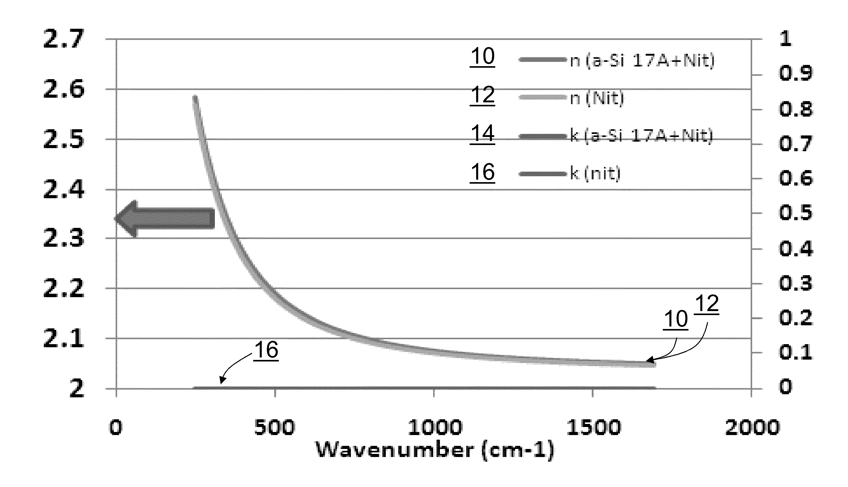
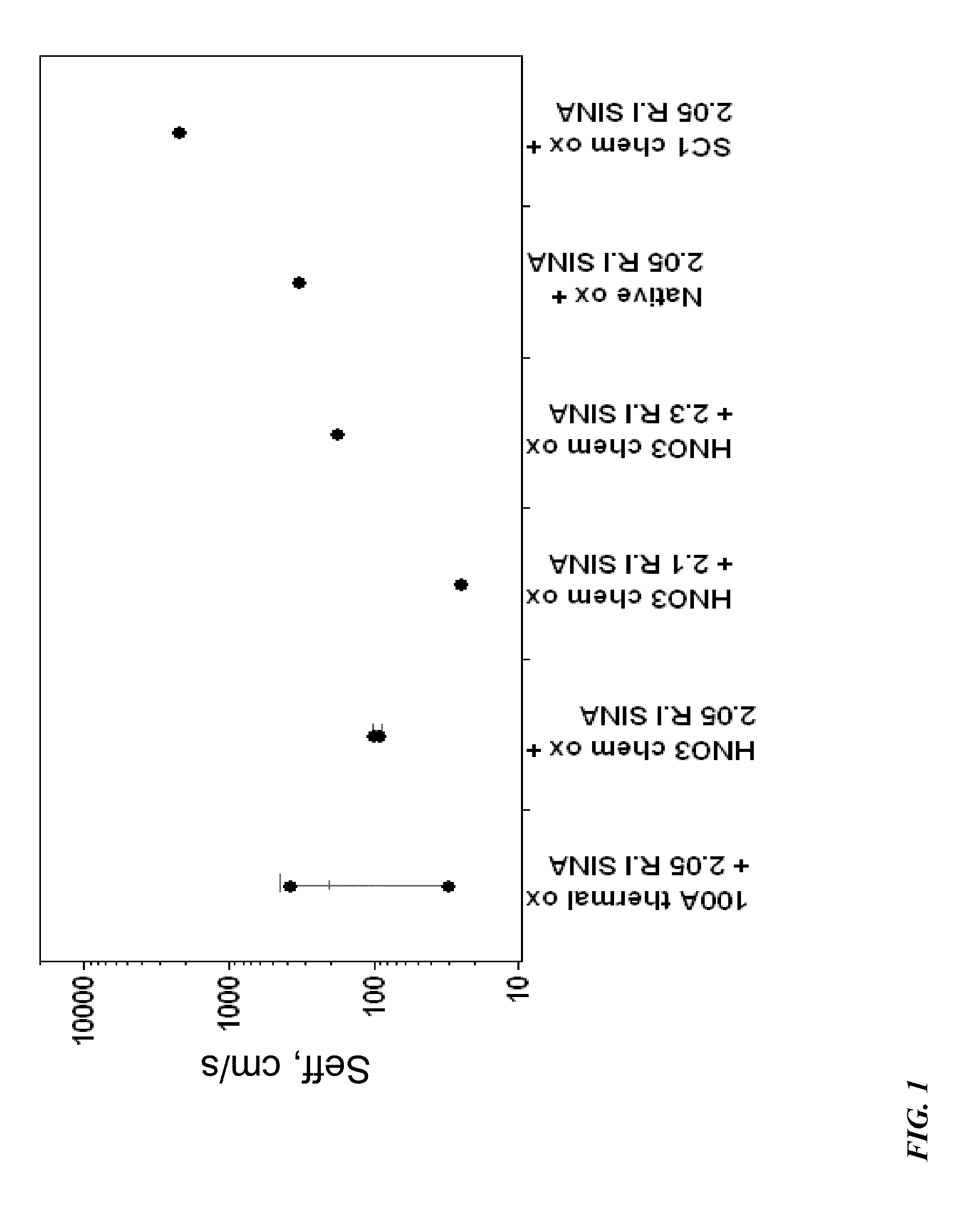
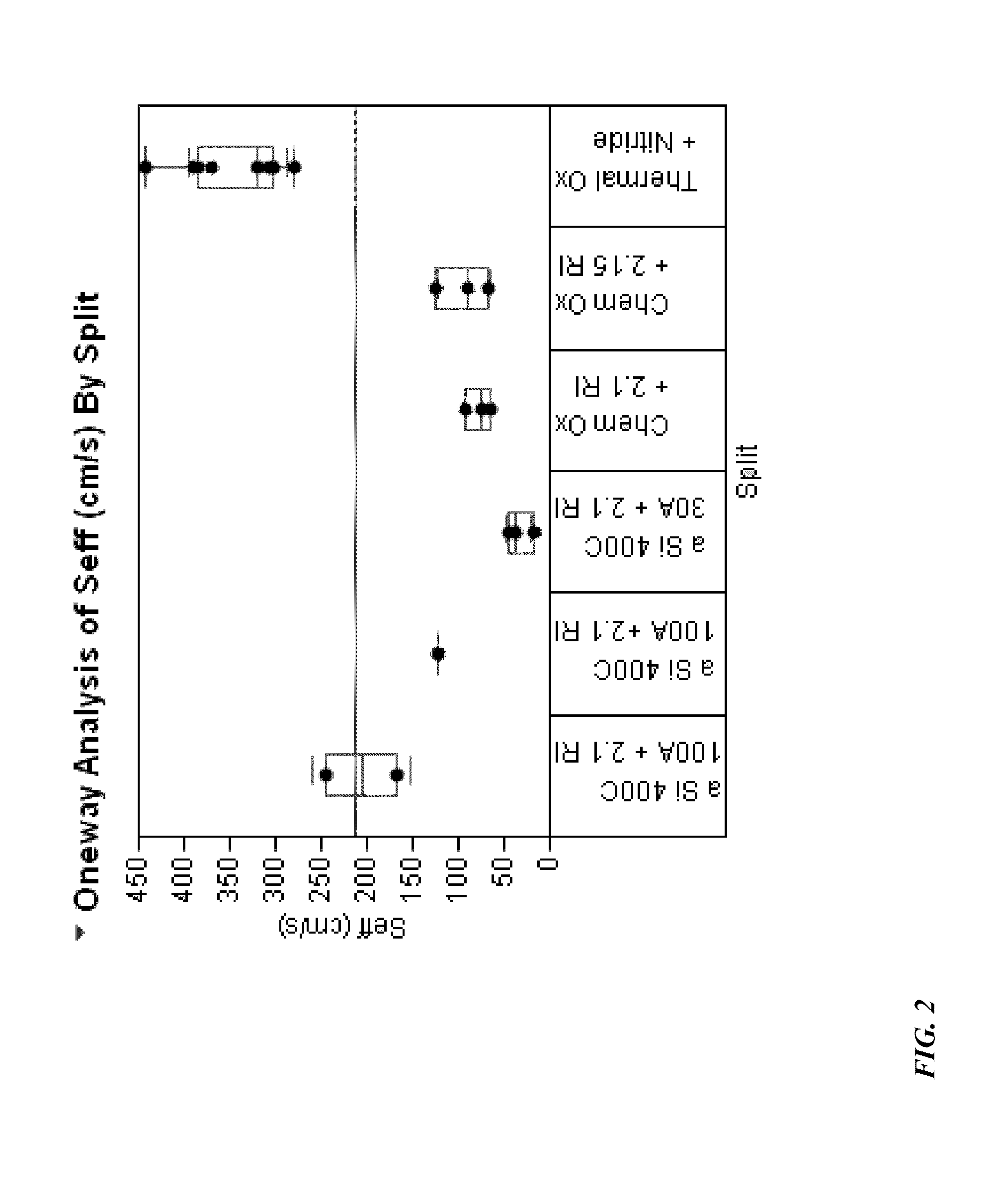
[0018]High-quality surface passivation is needed to obtain low surface recombination velocities and high effective minority carrier lifetimes on crystalline silicon substrates for various applications, including solar photovoltaic cells. Historically superior surface passivation techniques have included using a high temperature thermal oxidation process. However, these high temperature processes may be undesirable for the manufacture of thin film solar cells in part due to the mechanically weak nature of thin film silicon substrates. Thus, the present disc...


PUM

PropertyMeasurementUnit
temperatureaaaaaaaaaa
thicknessaaaaaaaaaa

Abstract

The disclosed subject matter provides a method and structure for obtaining ultra-low surface recombination velocities from highly efficient surface passivation in crystalline silicon substrate-based solar cells by utilizing a bi-layer passivation scheme which also works as an efficient ARC. The bi-layer passivation consists of a first thin layer of wet chemical oxide or a thin hydrogenated amorphous silicon layer. A second layer of amorphous hydrogenated silicon nitride film is deposited on top of the wet chemical oxide or amorphous silicon film. This deposition is then followed by annealing to further enhance the surface passivation.

Description

[0001]This application claims the benefit of provisional patent application 61 / 327,506 filed on Apr. 23, 2010, which is hereby incorporated by reference.FIELD[0002]This disclosure relates in general to the field of photovoltaics and solar cells, and more particularly to surface passivation of silicon solar cells.DESCRIPTION OF THE RELATED ART[0003]The performance of semiconductor crystalline silicon based devices, such as solar cells, depends strongly on minority carrier recombination in the bulk as well as surface regions of the cell itself. Consequently, reducing the surface recombination is of the utmost importance for these devices. Surface recombination effects are becoming progressively more important as silicon semiconductor device dimensions, such as solar cell wafer thickness, are reduced. The surface passivation of silicon using amorphous films based on hydrogenated silicon compounds has been the subject of intense research in recent years, particularly for solar cell appl...

Claims


Application Information

Patent Timeline
Patent Type & Authority Applications(United States)
IPC IPC(8): H01L31/0216H01L31/18H01L31/20B82Y20/00B82Y99/00
CPCH01L31/02167Y02E10/50H01L31/1868H01L31/1864Y02P70/50H01L31/0216H01L31/022425H01L31/0232H01L31/0236H01L31/02363H01L31/02366H01L31/04H01L31/18
Inventor MOSLEHI, MEHRDAD M.KRAMER, KARL-JOSEFDESHPANDE, ANANDRICOLCOL, RAFAELSEUTTER, SEAN M.
Owner BEAMREACH SOLAR INC
Why Eureka
Try Eureka