Phase shifter and power amplifier and magnetic resonance imaging apparatus

a power amplifier and phase shifter technology, applied in pulse manipulation, pulse technique, instruments, etc., can solve the problems of difficult to realize a phase shift of 180 degrees, influence system gain and noise, and too small phase shift, so as to reduce power loss, avoid self-excitation, and reduce insertion loss

Active Publication Date: 2011-12-01
GE MEDICAL SYST GLOBAL TECH CO LLC
View PDF10 Cites 6 Cited by
  • Summary
  • Abstract
  • Description
  • Claims
  • Application Information

AI Technical Summary

Benefits of technology

[0018]Compared with known phase shifters, the phase shifter and power amplifier and magnetic resonance imaging apparatus described herein have the following advantageous effects.
[0019]First, because the embodiments described herein include two 4-way switches and a bridge, when the two 4-way switches are selected to switch on the capacitance, a phase shift of 0 degrees is generated. When the two 4-way switches are selected to switch on the open circuit, a phase shift of 90 degrees is generated. When the two 4-way switches are selected to switch on the inductance, a phase shift of 180 degrees is generated. When the two 4-way switches are selected to switch on the short circuit (i.e. grounding), a phase shift of 270 degrees is generated. Moreover, a first phase shifter is continuously adjustable in shifting a phase from 0 degrees to 90 degrees, thus a phase shift that is continuously adjustable from 0 degrees to 360 degrees can be realized.
[0020]Second, because this type of phase shifter has little insertion loss, the matching of standing waves of the input and output ports are nice. This type of phase shifter is very important for a high power amplifier, as it not only can reduce power loss, but also can avoid self-excitation of power amplifier. Further, the phase shifter is easy to control and is convenient to use.

Problems solved by technology

However, the changes of the phase shift caused by this example is about 26 degrees, thus the range of phase shift is too small, while the insertion loss is rather large, which influences system gain and noise.
Compared to the phase shifter shown in FIG. 1, the phase shifter shown in FIG. 2 shifts phase in a broader range, however, it is difficult to realize a phase shift of 180 degrees.

Method used


Image

  • Phase shifter and power amplifier and magnetic resonance imaging apparatus
  • Phase shifter and power amplifier and magnetic resonance imaging apparatus
  • Phase shifter and power amplifier and magnetic resonance imaging apparatus

Examples


Embodiment Construction

[0025]The embodiments of the present invention will be described in detail as follows, however, the present invention is not limited to the following embodiments.

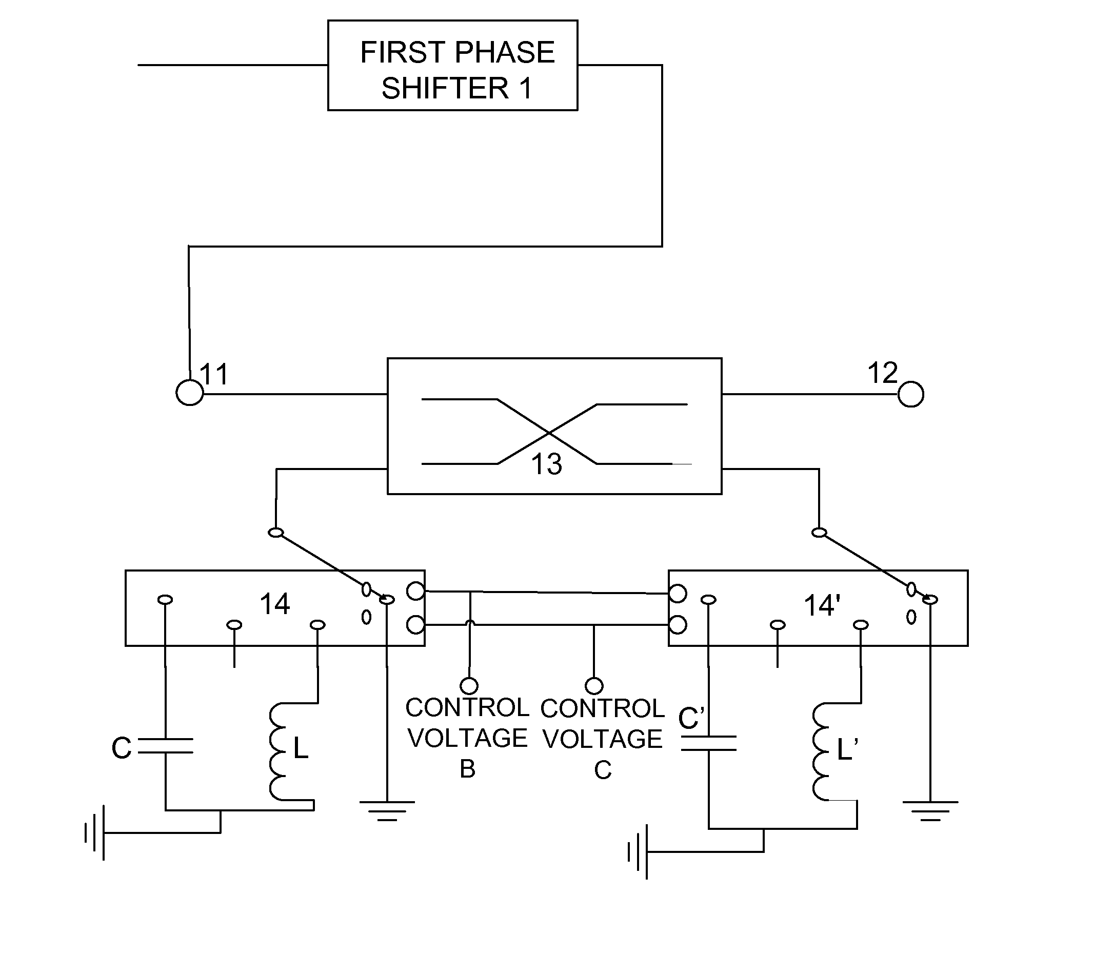
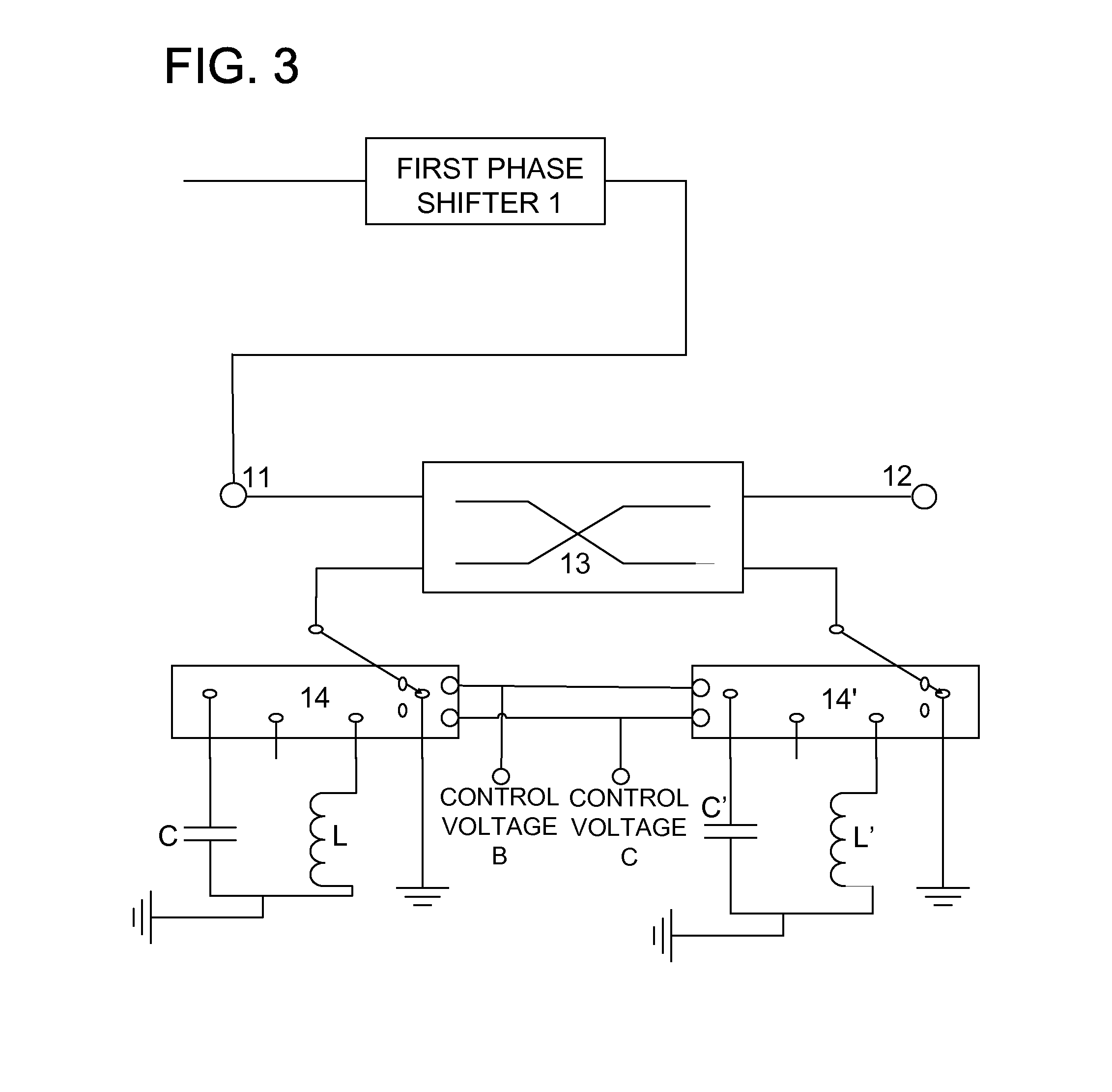
[0026]As shown in FIG. 3, the phase shifter includes a first phase shifter 1 that is continuously adjustable within a range of 0 degrees to 90 degrees, a bridge 13, and two 4-way switches 14 and 14′. An input end of the bridge 13 is connected to the 4-way switch 14, and an output end of the bridge 13 is connected to the 4-way switch 14′. The 4-way switch 14 is designed to selectively switch on one of a capacitance C, an inductance L, an open circuit, and a short circuit under the control of control voltages B and C. The 4-way switch 14′ is designed to selectively switch on one of a capacitance C′, an inductance L′, an open circuit, and a short circuit under the control of control voltages B and C. Another input end 11 of the bridge 13 is connected to an output end of the first phase shifter 1. Another output end of the brid...


PUM


Abstract

A phase shifter is provided. The phase shifter includes a first phase shifter that is continuously adjustable within a range of 0 degrees to 90 degrees, two 4-way switches each configured to selectively switch on one of a capacitance, an inductance, an open circuit, and a short circuit under control of a control voltage, and a bridge. A first input end and a first output end of said bridge are respectively connected to a first 4-way switch of the two 4-way switches. A second input end of said bridge is connected to an output end of said first phase shifter or a second output end of said bridge is connected to an input end of said first phase shifter.

Description

CROSS REFERENCE TO RELATED APPLICATIONS[0001]This application claims the benefit of Chinese Patent Application No. 201010193734.8 filed May 31, 2010, which is hereby incorporated by reference in its entirety.BACKGROUND OF THE INVENTION[0002]The present invention generally relates to very low frequency field, and especially relates to a phase shifter and power amplifier and magnetic resonance imaging apparatus in the nuclear magnetic resonance imaging technology.[0003]The nuclear magnetic resonance imaging technology is applied broadly in the medical field at present. The magnetic resonance imaging (MRI) is also called nuclear magnetic resonance imaging (NMRI), which is a diagnostic method that generates an image by atomic nucleus resonance in the magnetic field. The basic principle is forming an image by utilizing the inherent characteristics of atomic nucleus and the interaction of a magnetic field. A type of atomic nucleus closely related to tissues of the human body generates mag...

Claims


Application Information

Patent Timeline
Patent Type & Authority Applications(United States)
IPC IPC(8): H03H11/20
CPCG01R33/3607H03F1/32H03H11/22G01R33/36G01R33/3614H03H11/20
Inventor XING, HAOYANGLIU, YULIAO, ANMOUZHAO, CHENXING
Owner GE MEDICAL SYST GLOBAL TECH CO LLC
Why Eureka
Try Eureka