
Droopy bowtie radiator with integrated balun

a radiator and bowtie technology, applied in waveguide devices, resonant antennas, polarised antenna unit combinations, etc., can solve the problems of array antennas provided, limited bandwidth, and radiators with excellent bandwidth, and achieve easy manufacturing, high cross-polar isolation characteristics, and convenient attachment

Active Publication Date: 2011-12-01
RAYTHEON CO
View PDF7 Cites 29 Cited by
  • Summary
  • Abstract
  • Description
  • Claims
  • Application Information

AI Technical Summary

Benefits of technology

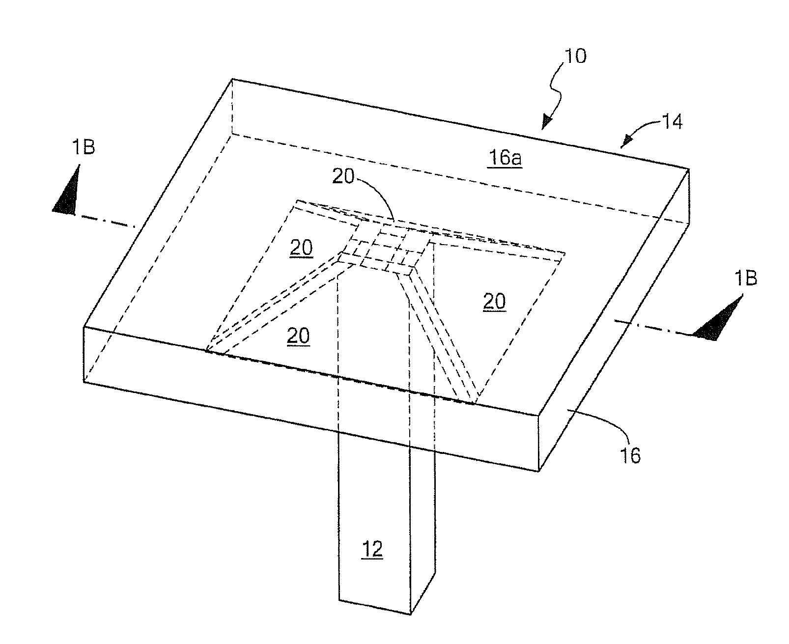
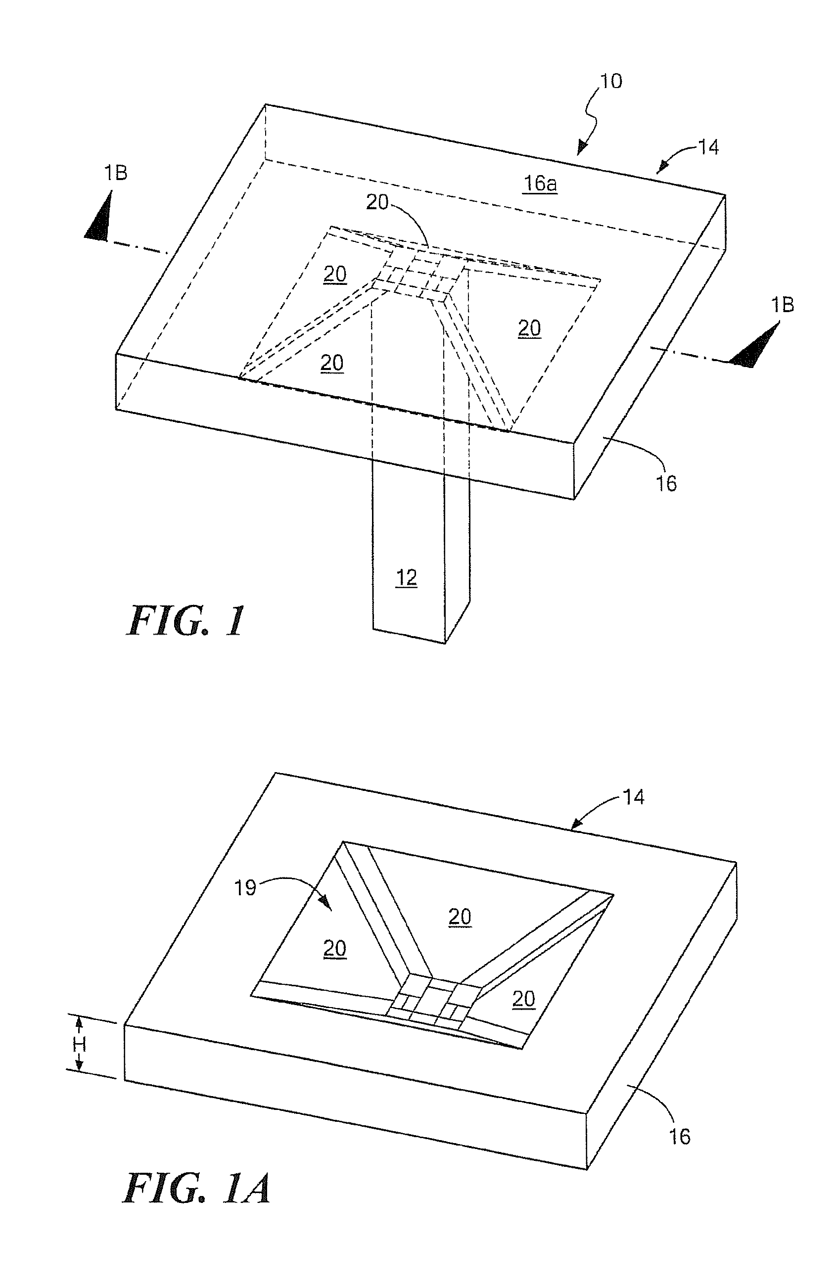
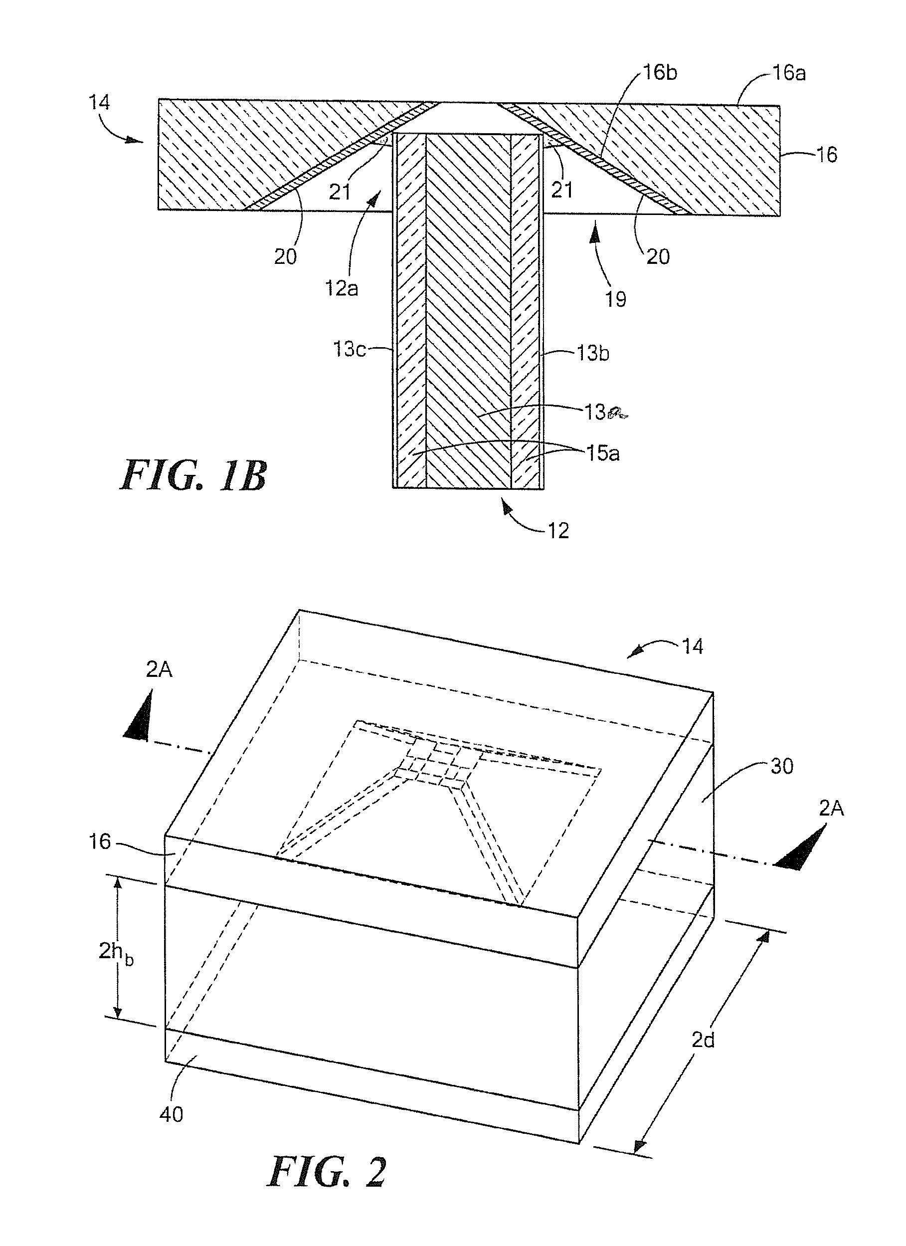
[0008]With this particular technique, a vertical feed line balun is provided. In one embodiment, the conductive member is provided having a square cross-sectional shape and a microstrip transmission line is disposed over each of the four external surfaces of the square conductive member to provide the balun as a quad vertical feed line balun made out of four individual transmission lines disposed over a common ground conductor. In one embodiment, the balun is provided as a Dyson balun and is used to feed a radiator such as a droopy bowtie radiator. By using a central conductive member and placing pairs of microstrip transmission lines on opposing surfaces of the central conductive member, the microstrip lines are physically and electrically isolated from each other (i.e. the microstrip lines are isolated by air gaps). This provides the balun having a high cross-polarization isolation characteristic. The same quad line can be used for operation in the S-, C-, and X-frequency bands, without changing balun parameters such as the cross-sectional dimensions of the quad vertical feeding line. The balun is mechanically stable which facilitates attachment to a printed circuit board (PCB) on one end, and to a radiator on the other end. Furthermore, since the quad vertical feeding line is mechanically symmetric, it lends itself to an easier assembly process than prior art approaches using pick and place equipment. The balun also provides coincident phase centers for orthogonal dipoles as well as flexibility in choosing array lattice geometry (rectangular, triangular, etc.).
[0011]Such a construction provides a balun having a high isolation characteristic between two transmission line pairs feeding two antennas. The high isolation characteristic is a result of the use of a central conductor as well as the use of a dielectric substrate having a relatively high relative dielectric constant (εr). Furthermore, the transmission lines disposed about the central conductor are isolated by air gaps which also helps to increase the isolation characteristic of the balun.
[0013]In one embodiment, the use of a dielectric material having a 25 mil thickness allows fabrication of a balun having dimensions that can be used in a variety of different frequency ranges (i.e. the same balun dimensions can be used over a wide range of frequencies) and which are very convenient for mechanical assembly. For example, the same dimensions can be used for baluns operating in the X-band frequency range as well as in the S-band and C-band frequency ranges. Other dielectric material thicknesses, may of course, also be used while also providing the ability to operate over a plurality of different frequency ranges and / or frequency bands. It should, however, be appreciated that the line feed impedance (i.e. the impedance of the quad vertical feeding line) depends, in part, upon the dielectric thickness and conductor line width (e.g. for a given line width, the dielectric material thickness affects the line feed impedance but the feeding line can be used over the S-, C- and X-Bands). In one embodiment, all balun transmission lines have the same characteristic impedance of about 30 Ohms per port, assuming that opposing ports are fed out of phase by 180 degrees. This means a 60 Ohm impedance per one dipole antenna fed with two ports in series, should provide an impedance match to a bowtie radiator which allows desired operation of the integrated balun and bowtie radiator.
[0015]With this particular arrangement, an integrated antenna-balun combination (also referred to herein as an integrated antenna element) is provided which allows operation over a relatively wide range of frequencies while at the same time providing a relatively high cross-polarization isolation characteristic.
[0017]In one embodiment, the radiator may be provided using an injection-molding technique and thus the radiator may be provided as a low-cost radiator. Such an element is suitable for use in an array.
[0018]In one embodiment, a quad vertical feeding line made out of four individual transmission lines disposed around a common ground conductor column feeds a radiator. In one embodiment, the ground conductor column is provided as a solid column having a rectangular or square cross-sectional shape. In some applications, a solid conductor may be preferred for mechanical purposes, but in other applications, a hollow or partially hollow conductor could also be used. The use of individual transmission lines provides the balun having a relatively high cross-polarization isolation characteristic and is easily manufactured using commercially available materials. The same quad line can be used for S-, C-, and X-band frequency ranges, without changing balun parameters (i.e. without changing the cross-sectional dimensions of the quad vertical feeding line). The balun is mechanically stable which facilitates attachment to a PCB on one end, and to a radiator on the other end. The balun also provides coincident phase centers for orthogonal disposed dipoles, and provides flexibility in choosing an array lattice geometry (rectangular, triangular, etc.).

Problems solved by technology

For example, with proper design, an array of dipole elements can have very good cross-polarization isolation characteristics in all scan planes; however, bandwidth is limited.
On the other hand, array antennas provided from notch radiators or Vivaldi radiators have excellent bandwidth, but relatively poor cross-polarization isolation off the principal axes.
Such a configuration typically results in an integrated antenna-balun assembly having good bandwidth but a poor cross-polarization isolation characteristic.
Furthermore, such a configuration is relatively difficult to assemble.

Method used


Image

  • Droopy bowtie radiator with integrated balun
  • Droopy bowtie radiator with integrated balun
  • Droopy bowtie radiator with integrated balun

Examples


Embodiment Construction

[0047]Before describing the various embodiments of the circuits, systems and techniques described herein, some introductory concepts and terminology are explained.

[0048]Reference is sometimes made herein to a quad line balun column coupled to an antenna element of a particular type, size and / or shape. For example, one type of antenna element is a so-called droopy bowtie turnstile antenna element having a size and shape compatible with operation at a particular frequency (e.g. 10 GHz) or over a particular range of frequencies (e.g. the C, S, L and / or X-band frequency ranges). Those of ordinary skill in the art will recognize, of course, that other shapes and types of antenna elements (e.g. an antenna element other than a droopy bowtie antenna element) may also be used with a quad line balun column and that the size of one or more antenna elements may be selected for operation at any frequency in the RF frequency range (e.g. any frequency in the range of about 1 GHz to about 100 GHz)....


PUM


Abstract

An antenna element and balun are described. The antenna includes a plurality of droopy bowtie antenna elements disposed on dielectric block and a feed point. The balun includes a central member having dielectric slabs symmetrically disposed on external surfaces thereof. At least one end of the balun is provided having a shape such that conductors on the dielectric slabs of the balun can be coupled to the the droopy bowtie antenna elements.

Description

CROSS-REFERENCE TO RELATED APPLICATIONS[0001]Not applicable.STATEMENT REGARDING FEDERALLY SPONSORED RESEARCH[0002]Not applicable.FIELD OF THE INVENTION[0003]This application generally relates to radio frequency (RF) circuits and more particularly to an RF antenna and integrated balun.BACKGROUND OF THE INVENTION[0004]As is known in the art, antenna elements or radiators used in phased array antennas typically have good bandwidth or good cross-polarization isolation, but not both. For example, with proper design, an array of dipole elements can have very good cross-polarization isolation characteristics in all scan planes; however, bandwidth is limited. On the other hand, array antennas provided from notch radiators or Vivaldi radiators have excellent bandwidth, but relatively poor cross-polarization isolation off the principal axes.[0005]Droopy bowtie elements disposed above a ground plane are a well known means for producing nominally circular polarized (CP) reception or transmissio...

Claims


Application Information

Patent Timeline
IPC IPC(8): H01Q1/50H03H5/00H01Q21/00H01Q9/04H01Q9/16
CPCH01P5/10H01Q21/26H01Q21/062H01Q9/28
Inventor PUZELLA, ANGELO M.MAKAROV, SERGEYMORRISON, PATRICK
Owner RAYTHEON CO
Learn More