3-D self-focusing gap plasmon generator for TAMR

a gap plasmon and plasmon generator technology, applied in the field of perpendicular magnetic recording, can solve the problems of limited coupling efficiency of wg light high cost of lds operating, and limited efficiency of wg light coupling into the edge plasmon mode, so as to achieve higher optical efficiency and reduce propagation loss

Active Publication Date: 2011-12-01
HEADWAY TECH INC
View PDF5 Cites 9 Cited by
  • Summary
  • Abstract
  • Description
  • Claims
  • Application Information

AI Technical Summary

Benefits of technology

[0015]Another object of at least one embodiment of the present invention has been to provide said apparatus with three dimensional self-focusing, thereby improving the coupling efficiency between the optical wave-guide and the plasmon generator as a result of ensuring a large overlap between the two modes.
[0016]Still another object of at least one embodiment of the present invention has been to achieve better thermal dissipation in the plasmon generator by providing a large volume of the metal film.
[0017]A further object of at least one embodiment of the present invention has been to facilitate placement and alignment of the hot spot formed in the recording medium, relative to the perpendicular write pole.
[0018]These objects have been achieved by the use of a Gap Plasmon Generator having a shape that is efficiently coupled to an optical waveguide, making it easier to use a TE polarized laser diode.
[0022]The structure of the invention has a higher optical efficiency than a Gap Plasmon Generator having a uniform cross-section normal to the z-direction because of 1) the larger overlap between the WG and GP modes in the entrance section, 2) adiabatic focusing and condensing of the GP by the second section's tilted metal walls, and 3) a reduced propagation loss since most of the optical energy is in the dielectric gap.

Problems solved by technology

LDs are not usually designed and fabricated for operation in the TM mode and their cost is often higher than that of LDs operating in the more commonly used transverse electric (TE) mode (whose polarization is in the x-direction).
Other critical limitations to the achievement of high optical efficiency have been documented in the prior art.
First, the efficiency of coupling WG light into the edge plasmon mode is limited by mode size mismatch between the diffraction-limited optical mode in the WG and the sub-diffraction-limited edge plasmon mode in the PG.
Second, propagation loss of the edge plasmon mode along the PG can be significant due to the high confinement of the edge plasmon mode.
Fourth, the plasmon antenna or the PG tend to be isolated and of limited volume so thermal management of these components to avoid heat damaging them could be challenging.

Method used


Image

  • 3-D self-focusing gap plasmon generator for TAMR
  • 3-D self-focusing gap plasmon generator for TAMR
  • 3-D self-focusing gap plasmon generator for TAMR

Examples


embodiment 1

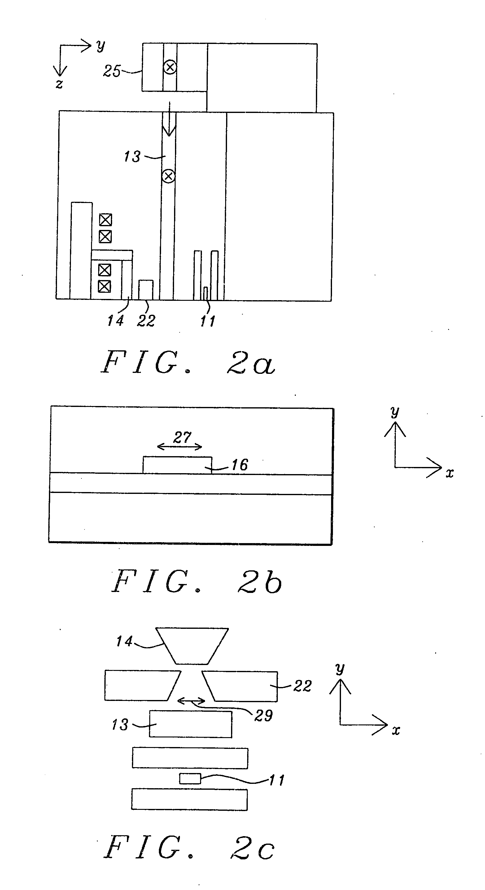
[0049]Embodiment 2 (FIGS. 9a-c) is the same as Embodiment 1 except that wave-guide 13 is recessed from the ABS so, in this configuration, coupling between Plasmon generator 22 and wave-guide 13 occurs where the two structures overlap.

embodiment 3 (figs.10a , 10b , and 10c)

[0050]Embodiment 3 (FIGS. 10a, 10b, and 10c) is the same as Embodiment 1 except that wave-guide 13 is not only recessed from the ABS, but is also located behind the entrance of Plasmon generator 22. In this configuration, the optical energy is directly coupled from the waveguide mode to the gap Plasmon mode.

DIFFERENCES AND ADVANTAGES

[0051]The main differences between the Self-focusing Gap Plasmon Generator of the present invention and the edge Plasmon generator of the prior art and their consequent advantages include:

[0052]1. Normally an Edge Plasmon generator needs a TM mode LD. This is a non-standard item and therefore expensive. However, the SGPG of the present invention can use a TE mode LD. This is readily available and therefore cheaper.

[0053]2. The SGPG has a three dimensional self-focusing shape while the EPG has a uniform cross section. Because of this, the SGPG has the following advantages:

[0054](i) Improved optical efficiency due to the better coupling efficiency of the W...


PUM

PropertyMeasurementUnit
separation distanceaaaaaaaaaa
areaaaaaaaaaaa
data densityaaaaaaaaaa

Abstract

A device for implementing thermally assisted magnetic recording, using a TE mode laser diode, and method for using it, are described. This device is shaped internally so as to provide three-dimensional self-focusing of plasmon radiation, thereby improving the coupling efficiency between the optical wave-guide and the plasmon generator as a result of ensuring a large overlap between these two modes.

Description

FIELD OF THE INVENTION[0001]The invention relates to the general field of perpendicular magnetic recording, particularly when thermally assisted, with special reference to the design and use of a plasmon generator for achieving this.BACKGROUND OF THE INVENTION[0002]Thermally assisted magnetic recording (TAMR) is expected to be capable of recording at 1˜10 Tb / inch2 data density. TAMR converts optical power into localized heating of the magnetic recording medium to temporarily reduce the field needed to switch the magnetizations of the grains that comprise the medium. Through a steep temperature gradient alone, or in conjunction with a high magnetic field gradient, data storage density can be improved to well beyond the current state-of-the-art magnetic recording technology.[0003]A TAMR head, in addition to the conventional magnetic recording features, usually comprises an optical wave-guide (WG) and a Plasmon antenna (PA) or Plasmon generator (PG). The WG acts as an intermediate path...

Claims


Application Information

Patent Timeline
Patent Type & Authority Applications(United States)
IPC IPC(8): G11B5/02
CPCG11B5/1278G11B2005/0021G11B2005/001G11B5/314
Inventor JIN, XUHUISMYTH, JOEDOVEK, MORIS
Owner HEADWAY TECH INC
Why Eureka
Try Eureka