Power conversion device and method for controlling thereof

a technology of power conversion device and power conversion method, which is applied in the direction of electric generator control, dynamo-electric converter control, dynamo-electric gear control, etc., can solve the problem of lowering the precision of motor control, and achieve stable, highly precise operation of motors.

Active Publication Date: 2011-12-01
HITACHI IND EQUIP SYST CO LTD
View PDF7 Cites 19 Cited by
  • Summary
  • Abstract
  • Description
  • Claims
  • Application Information

AI Technical Summary

Benefits of technology

[0012]Recently, motors increasingly tend to be highly efficient and compact and to generate less noise, and the above situation is thereby more likely to occur because, for example, the voltage saturation area is used and the carrier frequency is increased.
[0014]An object of the present invention is to provide a power conversion device that achieves phase current detection, based on a DC bus conductor, in which a restriction due to an upper limit or a lower limit for a voltage command value does not prevent current detection and enables stable, highly precise operation of a motor and to provide a method of controlling the power conversion device.
[0019]The preferred embodiments of the present invention can provide a power conversion device that achieves phase current detection, based on a DC bus conductor, in which a restriction due to an upper limit or a lower limit for a voltage command value does not prevent current detection and enables stable, highly precise operation of a motor, and can provide a method of controlling the power conversion device.
[0020]The preferred embodiments of the present invention can appropriately achieve current detection even under operation conditions in adverse environments in which, for example, high-speed operation is carried out, the triangular wave carrier frequency is high, and ringing noise lasts for a long period of time; under these conditions, current detection from a DC bus conductor is not possible in the conventional method.

Problems solved by technology

When this happens, a sufficient flow time cannot be assured for the pulsed current and a period during which the current cannot be detected occurs, causing a problem in that motor control precision is lowered.

Method used


Image

  • Power conversion device and method for controlling thereof
  • Power conversion device and method for controlling thereof
  • Power conversion device and method for controlling thereof

Examples


first embodiment

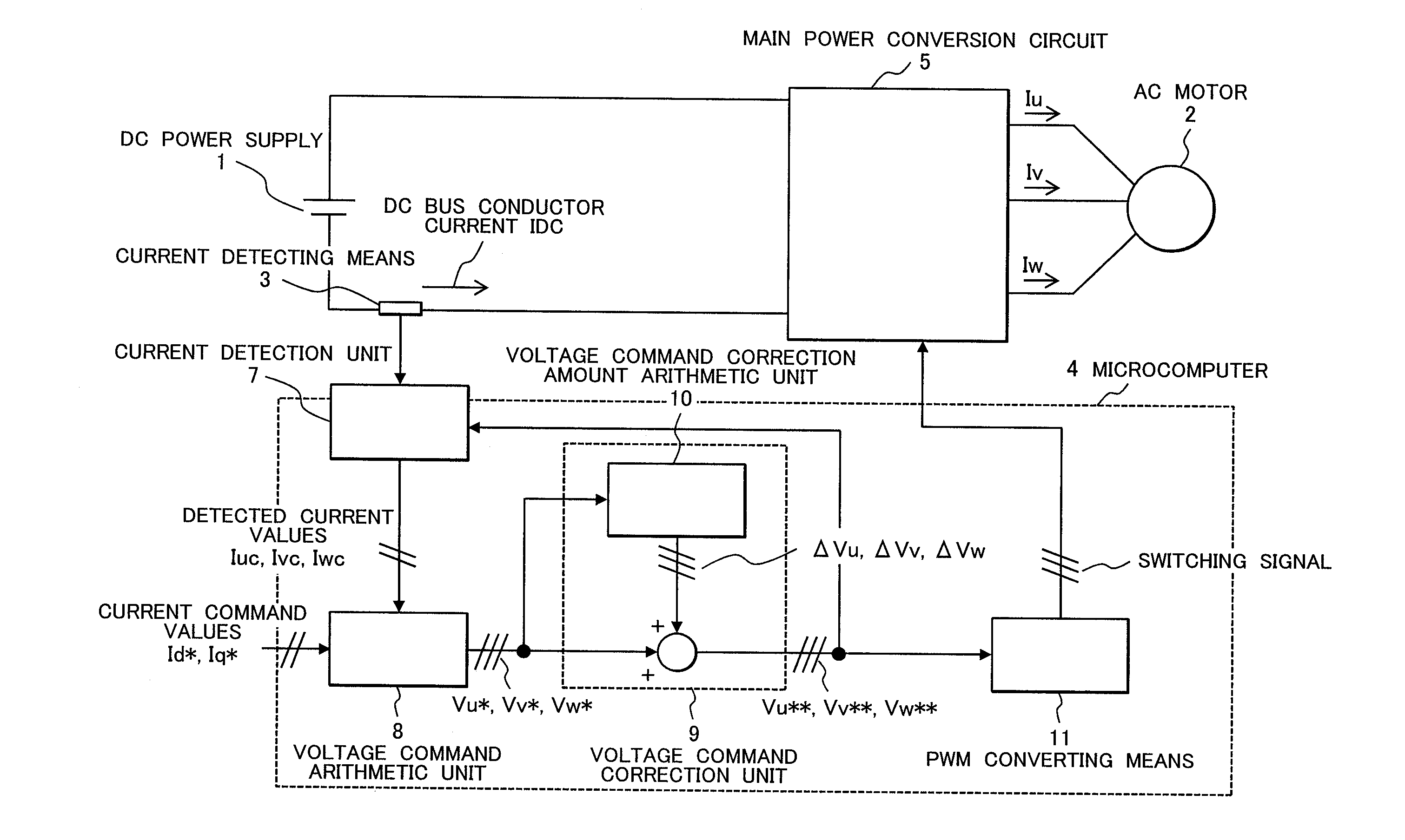
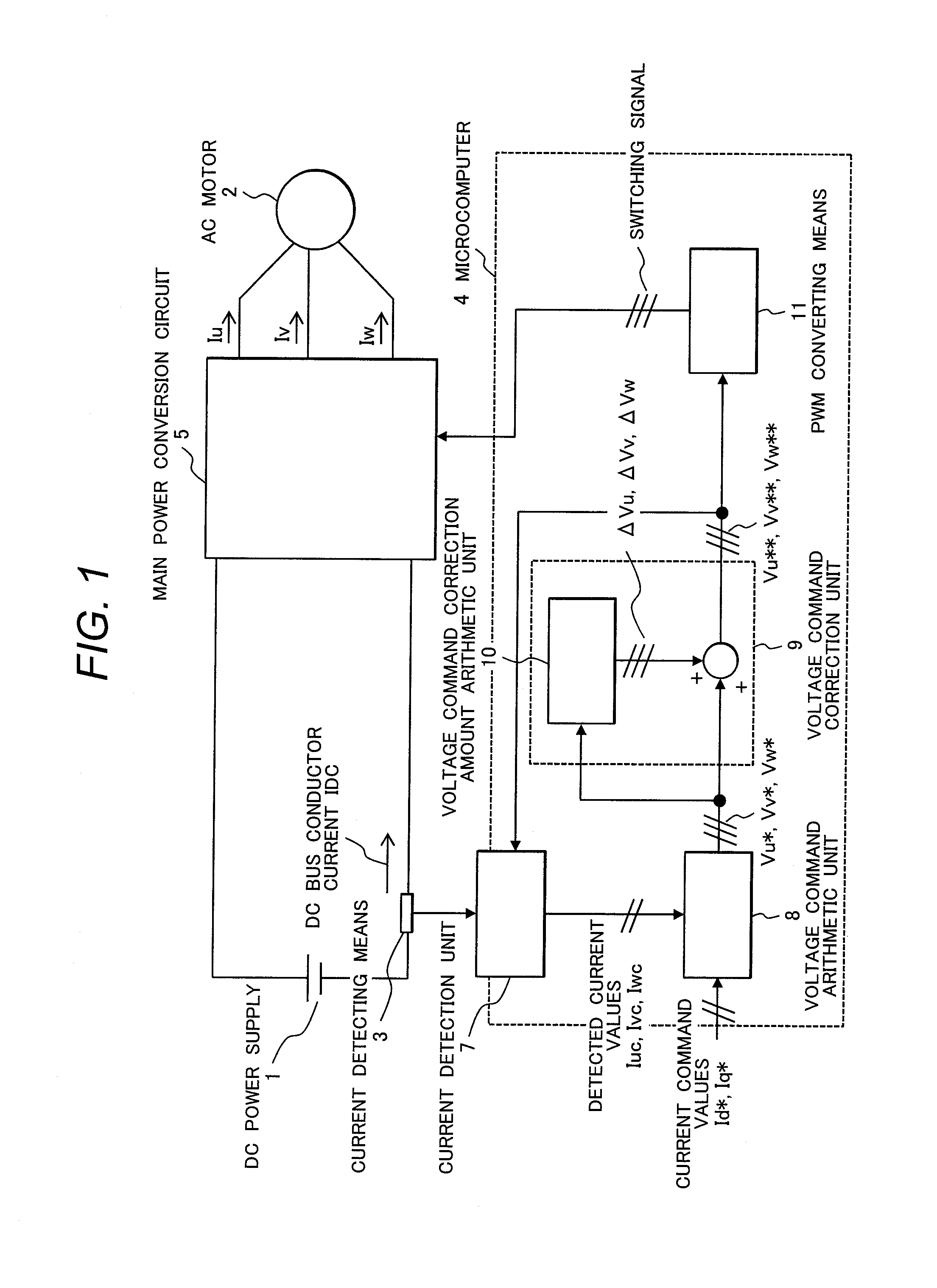
[0033]FIG. 1 is the entire structure of a power conversion device according to a first embodiment of the present invention. In FIG. 1, the interior of a microcomputer 4 indicates information flows and other portions indicate electric circuits (actual current flows).

[0034]In this embodiment, there are provided a DC power supply 1, a current detecting means 3 connected to a DC bus conductor, the microcomputer 4 that outputs a PWM signal on the basis of current information obtained from the current detecting means 3, a main power conversion circuit 5 that converts the electric power of the DC power supply 1 to AC electric power according to the PWM signal, and an AC motor 2 that works by using the converted electric power.

[0035]The microcomputer 4 has a current detecting part 7 that receives a DC bus conductor current IDC signal detected by the current detecting means 3, reproduces three-phase equilibrium currents Iuc, Ivc, and Iwc, and outputs these currents. The microcomputer 4 also ...

second embodiment

[0070]FIG. 4 illustrates a relation between the DC bus conductor current and three-phase voltages in a second embodiment of the present invention. Features of the second embodiment will be described with reference to this drawing. In this embodiment, the voltage command correction amount added in current detection as in the first embodiment is compensated in a period during which current detection is not carried out. Then, the second voltage command and first voltage command can be made the same, enabling a normal operation to be maintained. As for a compensation method, considering a period equal to N times the unit cycle as an adjustment period, as proposed in Patent Documents 2 and 3, correction amounts in a period during which current detection is not carried out may be set so that the average of correction amounts in all phases in the adjustment period is zero or substantially zero. In this embodiment, however, the intermediate phase is also corrected, so a problem arises in th...

fourth embodiment

[0083]FIG. 6 illustrates a relation between the DC bus conductor current and three-phase voltages in a fourth embodiment of the present invention. This embodiment is characterized in that the number N of unit cycles that determine the adjustment period is an odd number and a unit cycle in which detection is carried out is placed at the center of the adjustment period. FIG. 6 illustrates a case in which N is 3. The unit cycle for which k is 2 is the detection period, and the unit cycles for which k is 1 and 3 are the compensation cycles. The calculation of the voltage command correction amount in each detection period is carried out by using the method in the first embodiment, and the calculation of the correction amount in each compensation period is carried out by using the method in the second embodiment, so the following equations are set.

ΔV1[1]=ΔV1[3]=−ΔV10 / 2   (19)

ΔV1[1]=ΔV2[3]=−ΔV20 / 2   (20)

ΔV1[1]=ΔV3[3]=−ΔV30 / 2   (21)

[0084]If the voltage command exceeds Vmax or falls below

[00...


PUM


Abstract

In a power conversion device that includes a PWM converting means for generating a PWM pulse by comparing three-phase voltage commands with a triangular wave carrier signal, a power converter for converting between a DC voltage and a three-phase AC voltage by driving a switching element according to the PWM pulse, a current detecting means for detecting a pulsed current flowing through a DC bus conductor of a main circuit, and a voltage command correcting means for correcting three-phase voltage commands, which corrects the three-phase voltage commands so that a line voltage value between the maximum phase and an intermediate phase and a line voltage value between the intermediate phase and the minimum phase are each equal to or larger than a predetermined value, the maximum phase, intermediate phase, and minimum phase being determined in correspondence to momentary values of the three-phase voltage commands arranged in descending order, if the voltage command is outside an allowable upper limit or lower limit, not only the voltage command for the maximum phase and / or the minimum phase but also the voltage command for the intermediate phase are corrected.Accordingly, the inability to detect a current due to a restriction imposed by an upper limit or a lower limit for an output voltage is eliminated, and highly precise control of the power conversion device is achieved independently of the situation.

Description

FIELD OF THE INVENTION[0001]The present invention relates to a power conversion device that detects DC bus conductor current and obtains phase current information and to a method of controlling the power conversion device.BACKGROUND OF THE INVENTION[0002]Power conversion devices, typified by inverters, use pulse width modulation (PWM) to achieve a DC to AC conversion or AC to DC conversion function. Inverters are used in, for example, driving systems for synchronous motors, induction motors, and other AC motors (referred to below as motors).[0003]A power conversion device for driving a motor needs a means for detecting phase current to achieve precise control. Recently, methods of obtaining information about AC current flowing in a motor from DC bus current in a power conversion device, without having to use an external current detecting means such as a current sensor, are proposed in, for example, Patent Document 1, Patent Document 2, and Patent Document 3. These technologies elimi...

Claims


Application Information

Patent Timeline
Patent Type & Authority Applications(United States)
IPC IPC(8): H02M7/44H02M7/48H02P21/00H02P21/22H02P27/06H02P27/08
CPCH02M7/53871H02M1/12H02M1/15H02M7/5395H02M1/0009
Inventor ARAKAWA, YOICHIRONAGATA, KOICHIROARAO, YUUSUKEAOYAGI, SHIGEHISA
Owner HITACHI IND EQUIP SYST CO LTD
Why Eureka
Try Eureka