Electromagnetic pump

a technology of electromagnetic force and pump, which is applied in the direction of pump, positive displacement liquid engine, liquid fuel engine, etc., can solve the problem of unstable generation of electromagnetic force, and achieve the effect of improving performance and reducing siz

Active Publication Date: 2011-12-01
AISIN AW CO LTD
View PDF3 Cites 21 Cited by
  • Summary
  • Abstract
  • Description
  • Claims
  • Application Information

AI Technical Summary

Benefits of technology

[0008]The present invention provides an electromagnetic pump having improved performance and a reduced size.
[0009]An electromagnetic pump according to a first aspect of the present invention includes: a piston that is slidably provided in a cylinder and partitions a first fluid chamber and a second fluid chamber connected to an object to be operated; an electromagnetic portion that moves the piston forward by an electromagnetic force; an elastic member that moves the piston backward by applying an elastic force to the piston in a direction opposite to that of the electromagnetic force of the electromagnetic portion; a first on-off valve that allows working fluid to flow from outside into the first fluid chamber and prevents working fluid from flowing from the first fluid chamber to the outside; and a second on-off valve that is provided in a connecting flow passage that connects the first fluid chamber and the second fluid chamber to each other, allows working fluid to flow from the first fluid chamber into the second fluid chamber, and prevents working fluid from flowing from the second fluid chamber into the first fluid chamber. A capacity of the first fluid chamber reduces and a capacity of the second fluid chamber increases when the piston is moved forward, and the capacity of the first fluid chamber increases and the capacity of the second fluid chamber reduces when the piston is moved backward. A change in capacity of the first fluid chamber is larger than a change in capacity of the second fluid chamber in a reciprocating motion of the piston.
[0012]A fluid pressure of working fluid that is discharged from the second fluid chamber to the object to be operated when the piston is moved backward by the elastic force of the elastic member, may be larger than that of working fluid that is discharged from the first fluid chamber to the object to be operated via the second on-off valve and the second fluid chamber when the piston is moved forward by the electromagnetic force of the electromagnetic portion. Thus, the peak of a discharge pressure in each cycle of the electromagnetic pump can be set by the elastic force of the elastic member, whereby working fluid can be discharged without being affected by a change in electromagnetic force of the electromagnetic portion, which occurs, for example, when heat is generated.
[0013]The piston may include a cylindrical piston main body and a shaft portion that is connected to the piston main body and has an outer diameter smaller than that of the piston main body. The cylinder may include a slide surface on which the piston main body slides and a slide surface on which the shaft portion slides, where these slide surfaces are formed so that there is a difference in level therebetween in the cylinder. The second fluid chamber may be a space surrounded by the cylinder and the piston, with the piston being inserted in the cylinder. Thus, performance can be improved by merely performing simple processing.
[0014]The electromagnetic portion may include a mover that drives the piston and a case that accommodates the mover. The mover may move away from the case by the electromagnetic force when the electromagnetic portion is energized. The mover may move toward the case together with the piston by the elastic force of the elastic member when the electromagnetic portion is deenergized. By applying this structure to the first aspect of the present invention, working fluid in the second fluid chamber serves as a resistance when the piston is moved backward by the elastic force of the elastic member. This can prevent a collision between the mover and the case which occurs when the piston is moved backward fast, and thus, can reduce generation of abnormal noises such as a sound of the collision. As used herein, the “mover” includes a mover that is formed separately from the shaft portion of the piston, and a mover that is formed integrally with the shaft portion of the piston.
[0015]The first and second on-off valves may be built into the cylinder. This can make an overall system more compact when the electromagnetic pump is incorporated into the system. The second on-off valve may be built into the piston. In this case, the second on-off valve may include a main body formed integrally with the piston and an open / close member that opens and closes the central hole. The main body may include a central hole formed around the same axis as the piston and a through hole formed radially so as to communicate with the central hole. The central hole and the through hole may be used as the connecting flow passage that communicates the first fluid chamber and the second fluid chamber to each other. This enables a more compact electromagnetic pump to be implemented.

Problems solved by technology

Moreover, when the electromagnetic pumps are used continuously, generation of an electromagnetic force can become unstable due to, e.g., heat generated in an electromagnetic portion.

Method used


Image

  • Electromagnetic pump
  • Electromagnetic pump
  • Electromagnetic pump

Examples


Embodiment Construction

[0024]An embodiment of the present invention will be described below.

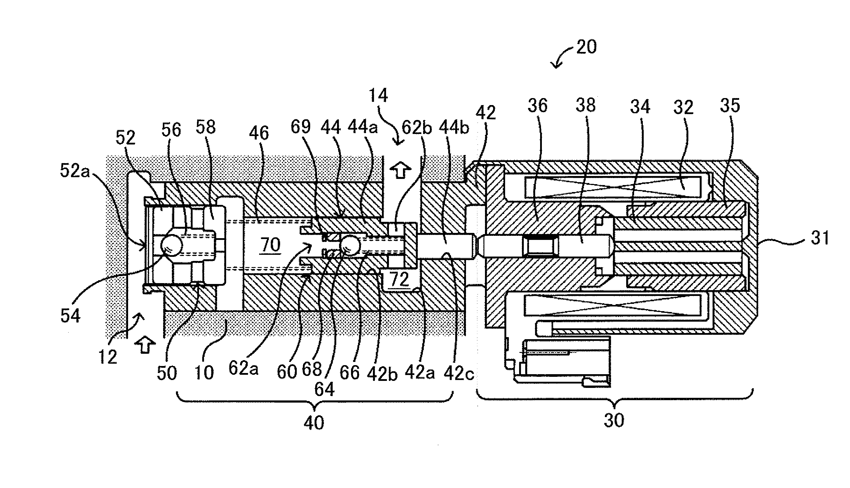
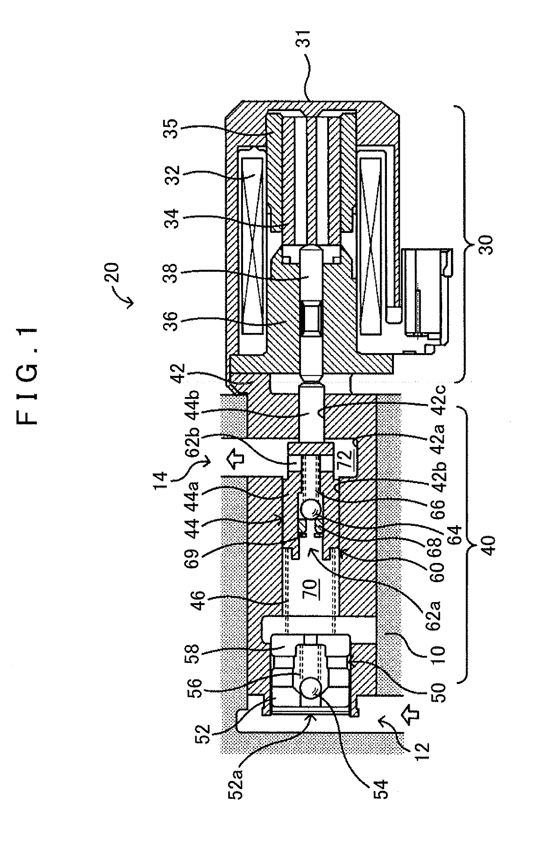
[0025]FIG. 1 is a structural diagram showing an overview of the structure of an electromagnetic pump 20 according to an embodiment of the present invention. As shown in FIG. 1, the electromagnetic pump 20 of the present embodiment is a piston pump for pressure-feeding hydraulic oil by reciprocating a piston 44 with an electromagnetic force, and includes a solenoid portion 30 and a pump portion 40. For example, this electromagnetic pump 20 is incorporated into a valve body 10 as a part of a hydraulic circuit for turning on / off clutches and brakes included in an automatic transmission that is mounted on a vehicle.

[0026]In the solenoid portion 30, an electromagnetic coil 32, a plunger 34 as a mover, and a core 36 as a stator are positioned in a case 31 as a bottomed cylindrical member. A magnetic circuit, which is formed by applying a current to the electromagnetic coil 32, attracts the plunger 34 to push out a shaft ...


PUM


Abstract

A piston is slidably provided in a cylinder and partitions a first pump chamber, and a second pump chamber connected to an object to be operated. A first on-off valve is provided between the first pump chamber and the outside. A second on-off valve is provided in a connecting flow passage that connects the first pump chamber and the second pump chamber to each other. When the piston is moved forward by an electromagnetic force of a solenoid portion, a capacity of the first pump chamber decreases, and a capacity of the second pump chamber increases. When the piston is moved backward by a biasing force of a spring, the capacity of the first pump chamber increases, and the capacity of the second pump chamber decreases. A pressure receiving area of the front face of the piston is larger than that of the back face thereof.

Description

BACKGROUND OF THE INVENTION[0001]1. Field of the Invention[0002]The present invention relates to an electromagnetic pump.[0003]2. Description of the Related Art[0004]One electromagnetic pump that has been proposed includes: a piston that is inserted in a cylinder, and forms a pump chamber; an electromagnetic coil for generating an attractive force that attracts a piston; and a spring member for pressing the piston in a direction opposite to the attractive force of the electromagnetic coil by a spring force (see, e.g., Japanese Patent Application Publication No. JP-A-2007-51567). When the electromagnetic coil is not excited (OFF), this electromagnetic pump introduces oil therein by moving the piston with the spring force of the spring member. When the electromagnetic coil is excited (ON), this electromagnetic pump discharges the introduced oil by moving the piston with the attractive force of the electromagnetic coil.[0005]Another proposed electromagnetic pump operates so that, when ...

Claims


Application Information

Patent Timeline
Patent Type & Authority Applications(United States)
IPC IPC(8): F04B35/04
CPCF04B17/044F04B53/12F04B17/048F04B53/14F04B53/162F05B2210/11F16F1/04F16F15/04F16F2230/22Y10S417/902
Inventor SHIMIZU, TETSUYAKATO, KAZUHIKOFUJII, NORIOMIISHIKAWA, KAZUNORI
Owner AISIN AW CO LTD
Why Eureka
Try Eureka