Bipolar secondary battery and method for producing the same

a secondary battery, bipolar technology, applied in the direction of cell components, sustainable manufacturing/processing, flat cell grouping, etc., can solve the problems of deterioration in battery output density and energy density, reduced power output of batteries, and disadvantages of connectors in space efficiency, etc., to achieve good seal durability and higher seal durability

Active Publication Date: 2011-12-01
NISSAN MOTOR CO LTD
View PDF1 Cites 48 Cited by
  • Summary
  • Abstract
  • Description
  • Claims
  • Application Information

AI Technical Summary

Benefits of technology

[0010]The present invention was made in view of the above circumstances. It is accordingly an object to provide a bipolar secondary battery in which seal means for sealing unit cells exhibits good seal durability.
[0011]The present inventors have made extensive researches to solve the above problems. During the process of the researches, the present inventors have changed the conventional concept that seal members are arra

Problems solved by technology

When the batteries are connected to each other via connectors, however, the power output of the batteries becomes decreased due to electrical resistance of the connectors.
Further, the batteries with the connectors are disadvantageous in terms of space efficiency.
That is, the use of the connectors leads to deteriorations in battery output density and energy

Method used


Image

  • Bipolar secondary battery and method for producing the same
  • Bipolar secondary battery and method for producing the same
  • Bipolar secondary battery and method for producing the same

Examples


example 1

[0091]A positive electrode active material paste was prepared by mixing 85 mass % of LiMn2O4 as a positive electrode active material, 5 mass % of acetylene black as a conduction aid, 10 mass % of polyvinylidene fluoride (PVdF) as a binder and an appropriate amount of N-methyl-2-pyrrolidone (NMP) as a slurry viscosity adjusting solvent. A negative electrode active material paste was prepared by mixing 85 mass % of Li4Ti5O12 as a negative electrode active material, 5 mass % of acetylene black as a conduction aid, 10 mass % of polyvinylidene fluoride (PVdF) as a binder and an appropriate amount of N-methyl-2-pyrrolidone (NMP) as a slurry viscosity adjusting solvent. Further, a collector was provided in the form of a conductive resin layer (thickness: 30 μm, volume resistivity in thickness direction: 1×10⁻² Ω·cm) containing polyethylene as a base material and carbon particles (average particle size: 0.8 μm) as a conductive filler. A positive electrode active material layer was formed on...

example 2

[0092]Bipolar electrodes were produced in the same manner as in Example 1, except for using polypropylene as the base material of the collectors.

example 3

[0093]Bipolar electrodes were produced in the same manner as in Example 1, except for using polyimide as the base material of the collectors.

Comparative Example 1

[0094]Bipolar electrodes were produced in the same manner as in Example 1, except for using SUS foil films (thickness: 30 μm) as the collectors.

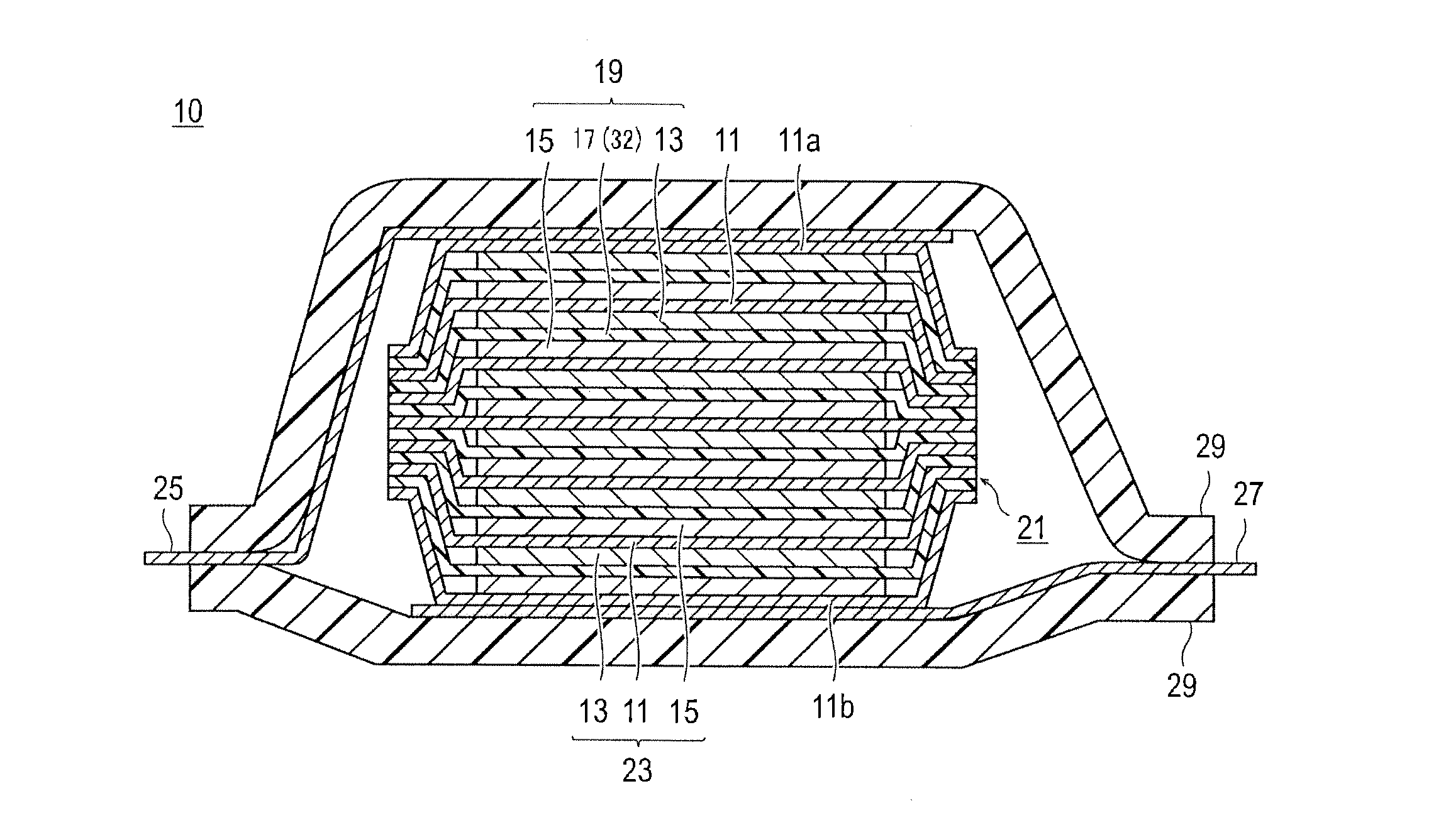
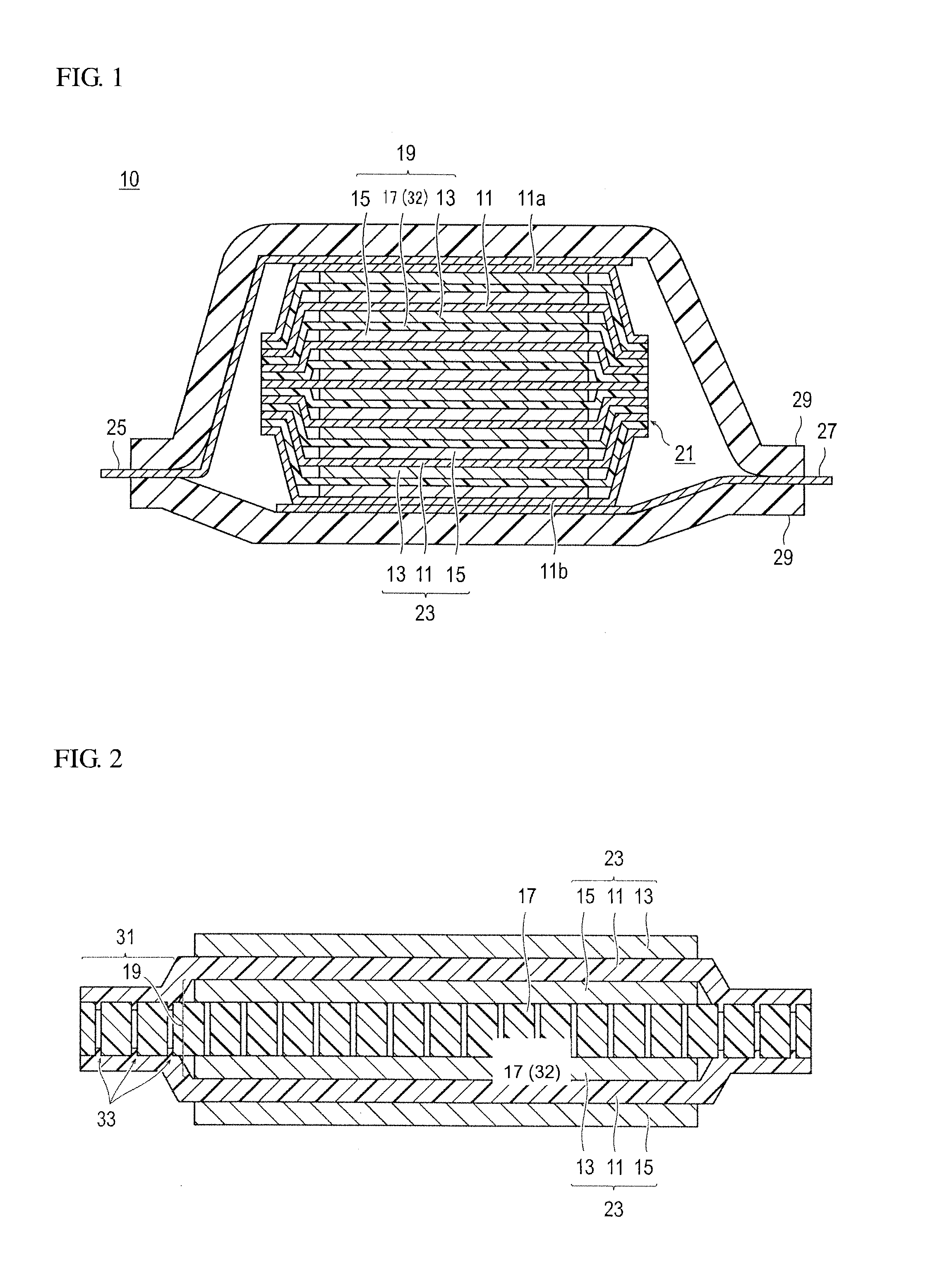
Production of Bipolar Secondary Battery


PUM

PropertyMeasurementUnit
Pore sizeaaaaaaaaaa
Areaaaaaaaaaaa
Particle sizeaaaaaaaaaa

Abstract

A bipolar secondary battery has a battery element that includes first and second bipolar electrodes each having a collector disposed with a conductive resin layer containing a first resin as a base material and positive and negative electrode active material layers formed on opposite sides of the collector and a separator containing a second resin as a base material, arranged between the first and second bipolar electrodes and retaining an electrolyte material to form an electrolyte layer. The positive electrode active material layer of the first bipolar electrode, the electrolyte layer and the negative electrode active material layer of the second bipolar electrode constitute a unit cell. A melting point of the first resin is lower than or equal to a melting point of the second resin. Outer peripheries of the collectors of the first and second bipolar electrodes and an outer periphery of the separator are fused together to thereby seal an outer peripheral portion of the unit cell.

Description

TECHNICAL FIELD[0001]The present invention relates to a bipolar secondary battery in which a seal portion for preventing leakage of an electrolytic solution from a unit cell has good seal durability and a production method thereof.BACKGROUND ART[0002]In recent years, hybrid electric vehicles (HEV), electric vehicles (EV) and fuel cell vehicles have been manufactured and sold and have been continuously developed from the viewpoint of environmental protection and fuel efficiency improvement. It is essential to make use of chargeable / dischargeable power sources in these so-called electric vehicles. As such power sources, secondary batteries e.g. lithium-ion batteries and nickel-metal-hydride batteries and electric double layer capacitors are used. In particular, the lithium-ion batteries are suitable for use in the electric vehicles because of high energy density and high resistance to repeated charge / discharge cycles. Various developments have been made in the lithium-ion batteries. F...

Claims


Application Information

Patent Timeline
IPC IPC(8): H01M4/24H01M10/04H01M50/417H01M50/423H01M50/426H01M50/491
CPCH01M4/667H01M10/0525H01M4/666H01M2/1673H01M4/668Y10T29/49114H01M2/1653H01M2004/029H01M10/0418Y02E60/122H01M10/0585Y10T29/4911H01M2/08Y02T10/7011Y02E60/10H01M50/46Y02P70/50H01M50/417H01M50/491H01M50/423H01M50/426H01M10/044Y02T10/70
Inventor HOSAKA, KENJIOBIKA, MOTOHARU
Owner NISSAN MOTOR CO LTD
Why Eureka
Try Eureka