Key interlock device

Active Publication Date: 2011-12-08
KK TOKAI RIKA DENKI SEISAKUSHO
View PDF25 Cites 10 Cited by
  • Summary
  • Abstract
  • Description
  • Claims
  • Application Information

AI Technical Summary

Benefits of technology

[0026]According to one embodiment of the invention, a key interlock device (or interlock unit) is constructed such that a rotation shaft part for rotatably supporting a link and a pin penetrating through the rotation shaft part are disposed on a virtual line extending from a line of force of a rotation force generated in the tangential direction of a cam shaft operated by a key (regular or authentic key). Since the rotation force from the cam shaft is received at the rotation shaft part and the pin, the burden of a l

Problems solved by technology

Although the retention type solenoid can hold the plunger at t

Method used


Image

  • Key interlock device
  • Key interlock device
  • Key interlock device

Examples


Embodiment Construction

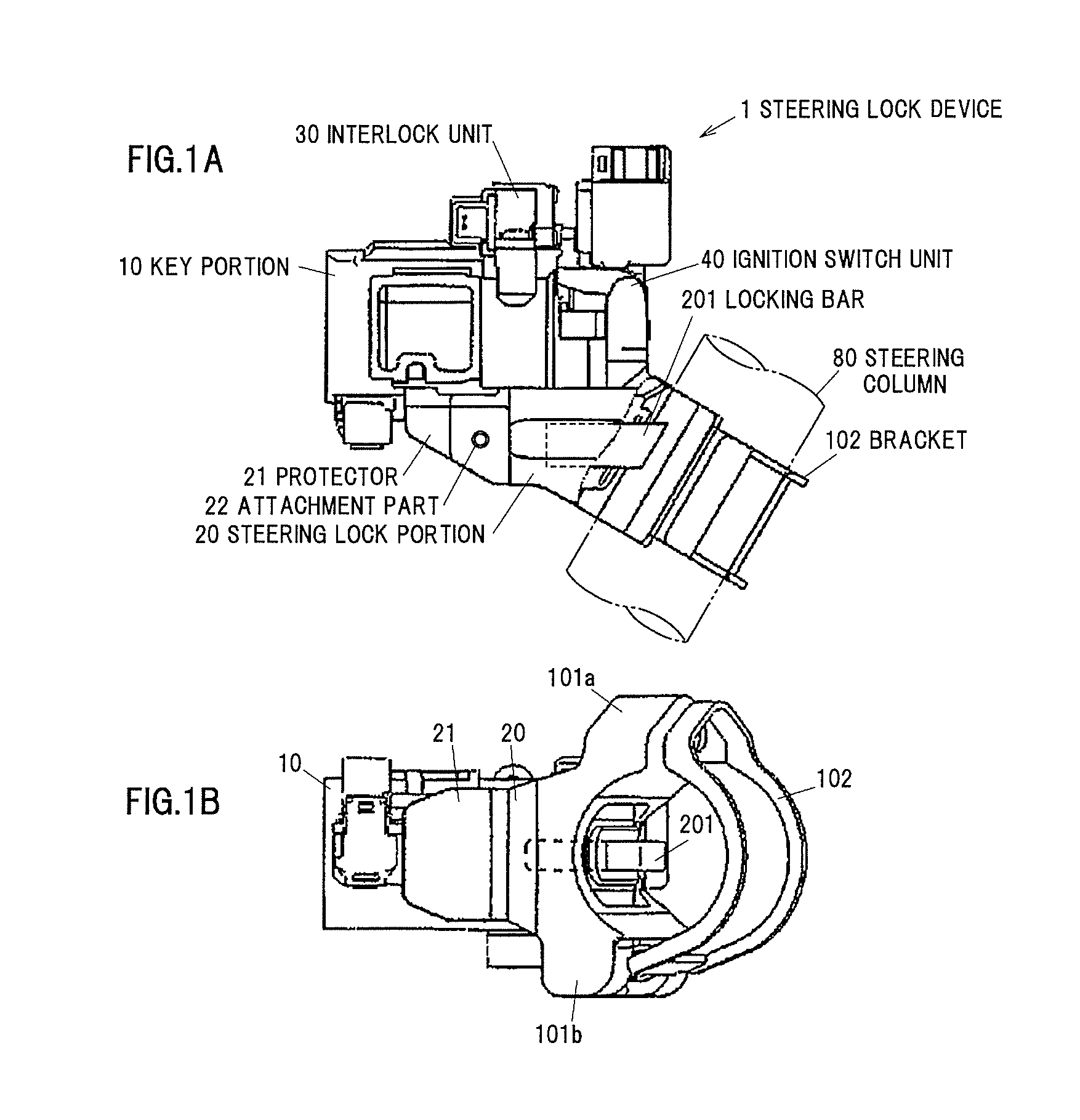
[0036]A preferred embodiment of the present invention will be detailed below with reference to drawings. First, a steering lock device 1 will be explained, that includes an interlock unit 30 as an interlock key device according to the present invention. Here, FIG. 1A is a side view schematically showing the steering lock device 1 using the interlock key device according to one embodiment of the present invention, in which a part of a bracket 102 for fixing a steering column 80 thereof is shown in a partially broken state. In addition, FIG. 1B is a bottom view schematically showing the steering lock device 1 shown in FIG. 1A. The steering lock device 1 is configured so as to include a key part 10, a steering lock part 20, the interlock unit 30 and an ignition switch unit 40.

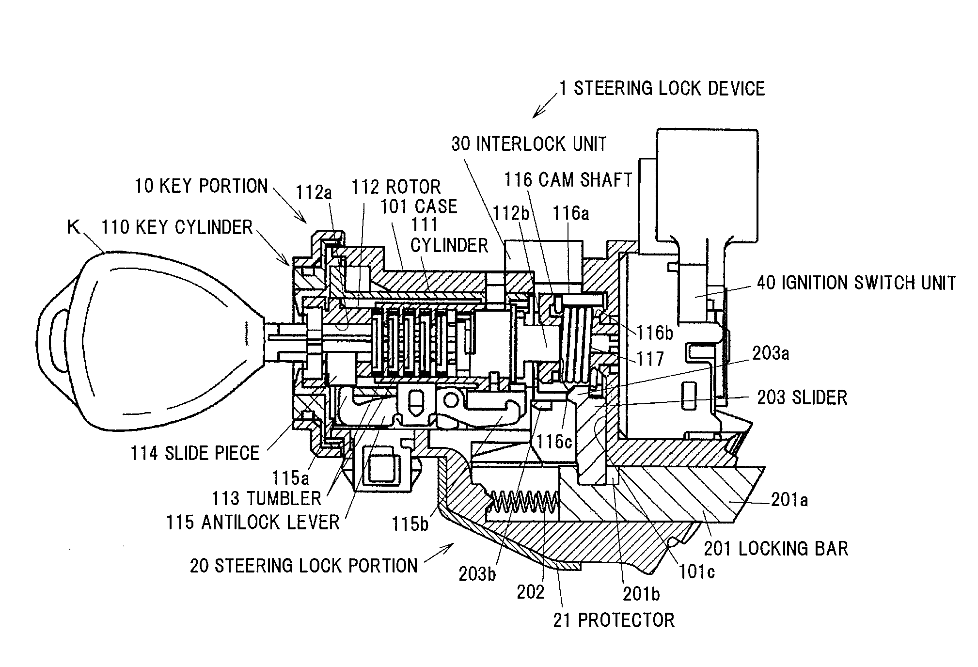
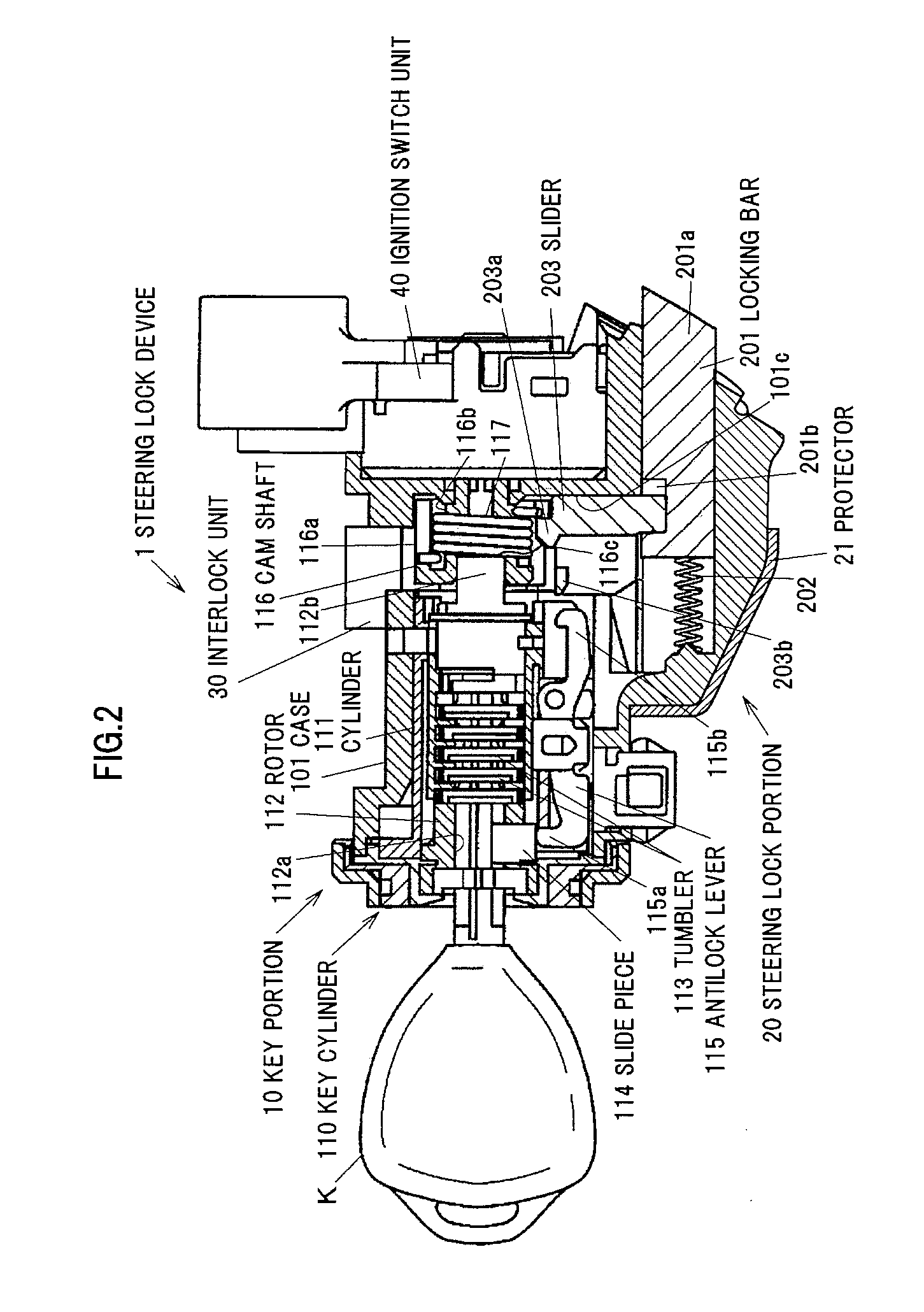
[0037]FIG. 2 is a longitudinal cross-sectional view schematically showing an inner structure of the steering lock device 1. A case 101 of the steering lock device 1 is integrally formed of a metal such as zinc die...


PUM


Abstract

A key interlock device includes a solenoid that holds a plunger when the solenoid is excited, and a link member that includes a shaft around which the link member is rotatable, and engages with the plunger so as to transmit a restraining force opposing an operation force of a key when the solenoid is excited. The shaft of the link member is disposed on a virtual line extending from a line of force of the operation force of the key. The key interlock device may include an engaging part through which the key interlock device is attached to a body of a steering lock device and which is disposed behind the shaft to which the operation force of the key applies.

Description

[0001]The present application is based on Japanese patent application No. 2010-131109 filed on Jun. 8, 2010, the entire contents of which are incorporated herein by reference.BACKGROUND OF THE INVENTION[0002]1. Field of the Invention[0003]This invention relates to a key interlock device that is attached to a steering lock device for a vehicle.[0004]2. Description of the Related Art[0005]Steering lock devices have been popularized that are equipped with a key interlock device to restrain a steering key (i.e., ignition key) from being turned form an “ACC” position to “LOCK” position when the vehicle is driven. The key interlock device uses an attraction type solenoid that is operable to attract a plunger when it is excited (e.g., JP-A-2000-229557).[0006]The attraction type solenoid operates to attract the plunger when a drive current is fed (i.e., the solenoid is excited or energized), so that a problem arises that the power consumption increases. Therefore, in recent years, the key i...

Claims


Application Information

Patent Timeline
IPC IPC(8): B60R25/02B60R25/023B60R25/021
CPCB60R25/02153Y10T70/5956Y10T70/5664B60R25/02
Inventor TAMEZANE, TAKUMIYOSHIDA, HIROSHINOMICHI, DAISUKE
Owner KK TOKAI RIKA DENKI SEISAKUSHO
Why Eureka
Try Eureka