Ultra-low-power occupancy sensor

Inactive Publication Date: 2011-12-08
WILLDEN JEREMY P
View PDF8 Cites 8 Cited by
  • Summary
  • Abstract
  • Description
  • Claims
  • Application Information

AI Technical Summary

Benefits of technology

[0014]This present invention provides a passive infrared (PIR) motion detector having dramatically reduced power consumption compared with those of the prior art. The new PIR motion detector reduces the gain stages of the device to no more than one, eliminates the window comparator required by prior-art devices, and employs a much more sensitive processor to detect the signal from the PIR sensor. The signal from the PIR sensor is amplified by a single stage amplifier. As an example, if the processor wakes up once per second and measures the output of the amplifier, any change in the measurement is an indication of motion. In general, the output of the amplifier is periodically measured by a microcontroller and monitored for changes. Though unlikely, it is conceivable that a person moving through the room at a controlled speed would produce changes on the sensor only during the time between measurements. To prevent this situation, a peak detector circuit may be added in between the amplification stage and the processor. Changes that occur in between measurements will be captured by the peak detector, and subsequently provided to the processor at the next measurement time. The decay time of the peak detector is adjusted to be long enough so the signal does not decay before the next measurement. Not only does the peak detector circuit enhance reliability of detection, but it also enables even greater energy savings by allowing the detection signal to be stored during times while the microcontroller is in a sleep mode. Common low-power eight-bit microcontrollers draw 5 to 10 milliamps of current when awake and running at the full clock rate. However, when in sleep mode, they draw only 1-2 microamps. Some newer microcontrollers require about one-twentieth the power of the most efficient common low-power eight-bit microcontrollers—drawing as little as 50 nanoamps when in sleep mode. If the duty cycle is limited to 1 percent (awake only 10 milliseconds), and the full clock rate of the microcontroller is used for only a dozen or so microseconds, and slowed to a tiny fraction (i.e., 1/32) of the full clock rate during the remainder of the awake period, then an integration of current draw during consecutive sleep and awake cycles can be between 1 and 2 microamps. If the PIR sensor is being used in a circuit that wirelessly transmits signals which are coded to notify a remote receiver of a change in occupancy status, the transmission of those signals over an interval of 10 to 40 milliseconds may require a power expenditure that is c

Problems solved by technology

In the case of the embodiment having a single amplification stage, this results in a lower signal bandwidth than traditional devices.
However, the

Method used


Image

  • Ultra-low-power occupancy sensor
  • Ultra-low-power occupancy sensor
  • Ultra-low-power occupancy sensor

Examples


Embodiment Construction

)

[0021]The various aspects of the invention will be now be described in detail with reference to the attached drawing figures. Drawing FIGS. 2 through 4.

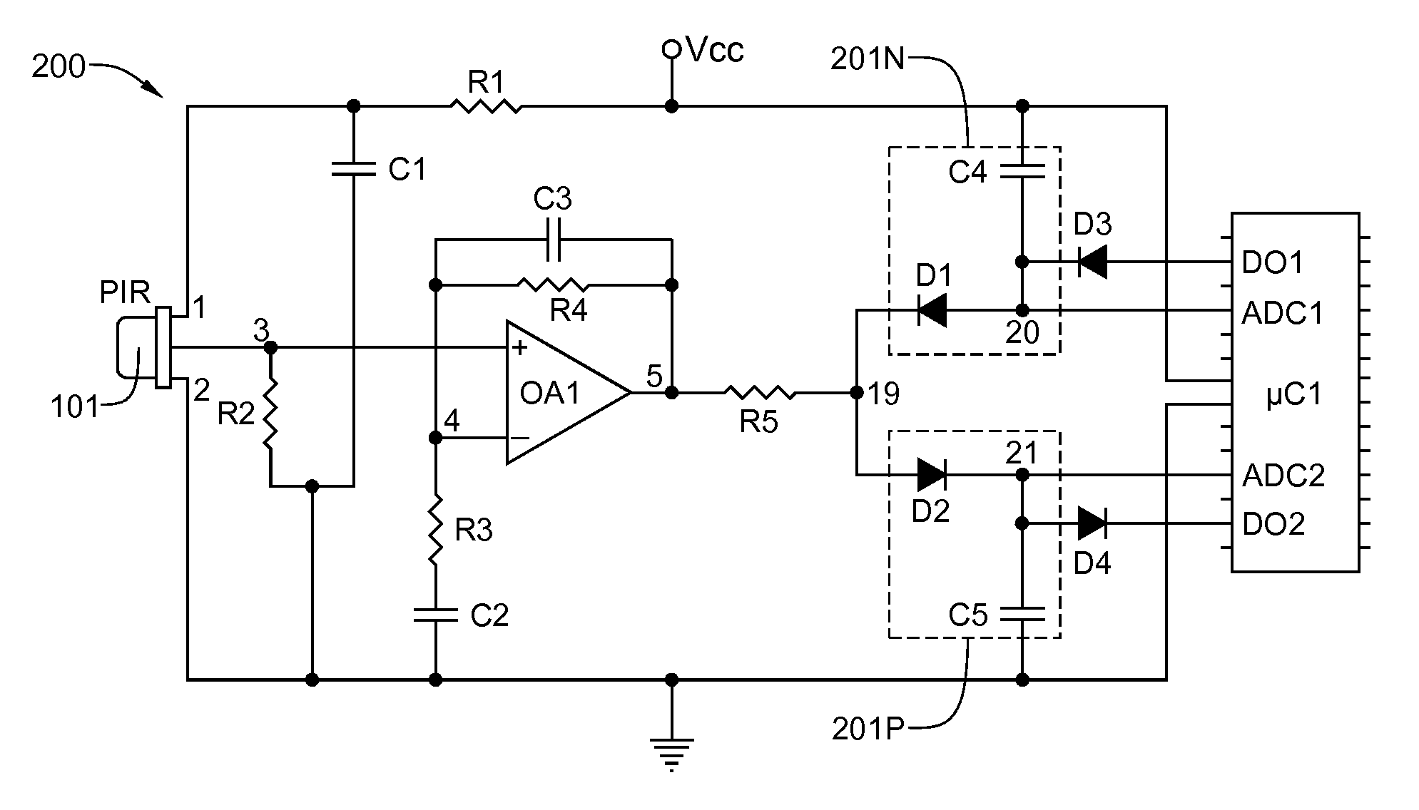
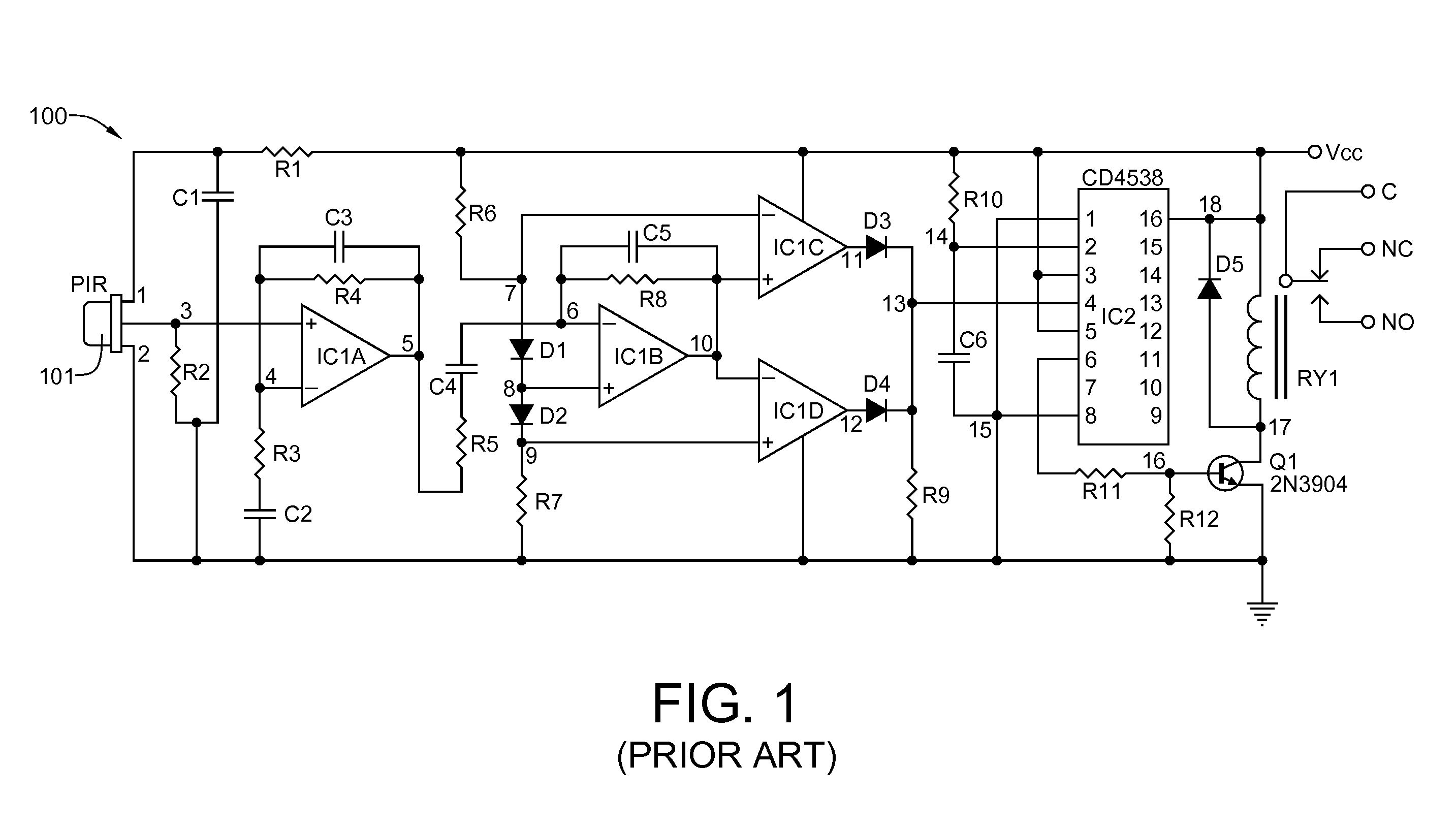
[0022]Referring now to FIG. 2, a first embodiment motion detector circuit 200, assembled in accordance with the present invention, includes a PIR sensor 201, Suggested component values are as follows: R1=10KΩ; R2=100KΩ; R3=10KΩ; R4=1MΩ; R5=1MΩ; C1=10 μf; C2=10 μf; C3=0.1 μf; C4=10 μf; and C5=10 μf. The front end of circuit 200 is functionally identical to the prior art motion detector circuit 100 of FIG. 1 up to the output of the first amplification stage, with the exception that a quad operational amplifier is not used. PIR sensor 101 is connected directly to ground through terminal 2. It is also connected to Vcc at terminal 1. C1 and R1 act as filters between the PIR sensor 101 and Vcc, as even tiny fluctuations in Vcc could perturb the PIR sensor, thereby causing output fluctuations that might well result in false occupancy detec...


PUM


Abstract

Passive IR sensor detection circuitry is provided that consumes eighty to ninety percent less power than conventional PIR sensor detection circuitry. Whereas prior art PIR sensor detection circuitry employs multiple amplification stages, to boost the power of the weak sensor signal, and a window comparator to determine whether an occupancy condition exists, the present invention uses, at most, a single amplification stage and no window comparator. In place of multiple amplification stages and a window comparators, the PIR sensor circuitry of the present invention uses a sensitive microcontroller to both detect and process the signal. A peak detector can be added just before the signal—whether amplified or not—is received by the microcontroller. Decay time of the peak detector is adjusted so that the signal will not substantially decay between measurements.

Description

[0001]This application has a priority date based on Provisional Patent Application No. 61 / 351,143, which has a filing date of Jun. 3, 2010, and is titled ULTRA-LOW POWER OCCUPANCY SENSOR.BACKGROUND OF THE INVENTION[0002]1. Field of the Invention[0003]The present invention generally relates to passive infrared (PIR) motion detectors and, more particularly, to low-power PIR motion detectors having no more than one amplification stage and no window comparator.[0004]2. History of the Prior Art[0005]Infrared (IR) radiation is electromagnetic radiation having a wavelengths that are longer than those of visible light and shorter than those assigned to microwave radiation. IR radiation is assigned wavelengths between 0.7 and 300 μm, which equates to a frequency range of approximately 1 to 430 teraherz. Bright sunlight provides an irradiance of just over 1 kilowatt per square meter at sea level. Of this energy, 527 watts is infrared radiation, 445 watts is visible light, and 32 watts is ultr...

Claims


Application Information

Patent Timeline
IPC IPC(8): G01J5/10
CPCG08B13/191
Inventor WILLDEN, JEREMY P.
Owner WILLDEN JEREMY P
Why Eureka
Try Eureka