Arrangement for and method of generating uniform distributed illumination pattern for imaging reader

an imaging reader and distribution pattern technology, applied in the direction of instruments, photoelectric discharge tubes, sensing by electromagnetic radiation, etc., can solve the problems of poor coupling efficiency poor use of single led and single cylindrical lens, etc., to improve the coupling efficiency between light source and optical component, improve light throughput, and enhance reading performance

Active Publication Date: 2011-12-08
SYMBOL TECH LLC
View PDF1 Cites 25 Cited by
  • Summary
  • Abstract
  • Description
  • Claims
  • Application Information

AI Technical Summary

Benefits of technology

[0013]In accordance with this invention, the optical component forms the distributed illumination pattern on and along the symbol with a uniform intensity not dominated by optical aberrations or abrupt intensity transitions. The coupling efficiency between the light source and the optical component is much improved, thereby increasing light throughput, enhancing reading performance, and improving visibility of the distributed illumination pattern. Reader ergonomics is enhanced.

Problems solved by technology

Although generally satisfactory for its intended purpose, the use of the single LED and the single cylindrical lens has been problematic, because the distributed illumination pattern typically has a height taller than that desired, does not have sharp edges, is dominated by optical aberrations, and is nonuniform in intensity since the light intensity is brightest along an optical axis on which the LED is centered, and then falls off away from the axis, especially at opposite end regions of the distributed illumination pattern.
Also, the coupling efficiency between the LED and the cylindrical lens has been poor.
Adding an aperture stop between the LED and the cylindrical lens will improve the sharpness (i.e., shorten the height) of the distributed illumination pattern, but at the cost of a poorer coupling efficiency and a dimmer distributed illumination pattern that, of course, degrades reading performance.
However, this further increases cost, introduces more optical aberrations, and further reduces coupling efficiency.
Also, the illumination light emitted by the pair of LEDs overlap at a central region of the distributed illumination pattern, thereby creating a bright, “hot” spot and abrupt light intensity transitions in the distributed illumination pattern, all of which can cause reading performance to deteriorate.
This, in turn, reduces resolution at the far range of working distances relative to the window and also spreads the illumination over a wider area, thereby reducing its intensity and again decreasing reading performance.
Known imaging readers insure such alignment by configuring the handle and the PCB therein to be strictly vertical, but this results in a housing with a poor ergonomic design that increases operator fatigue and discomfort and decreases productivity.

Method used


Image

  • Arrangement for and method of generating uniform distributed illumination pattern for imaging reader
  • Arrangement for and method of generating uniform distributed illumination pattern for imaging reader
  • Arrangement for and method of generating uniform distributed illumination pattern for imaging reader

Examples


Embodiment Construction

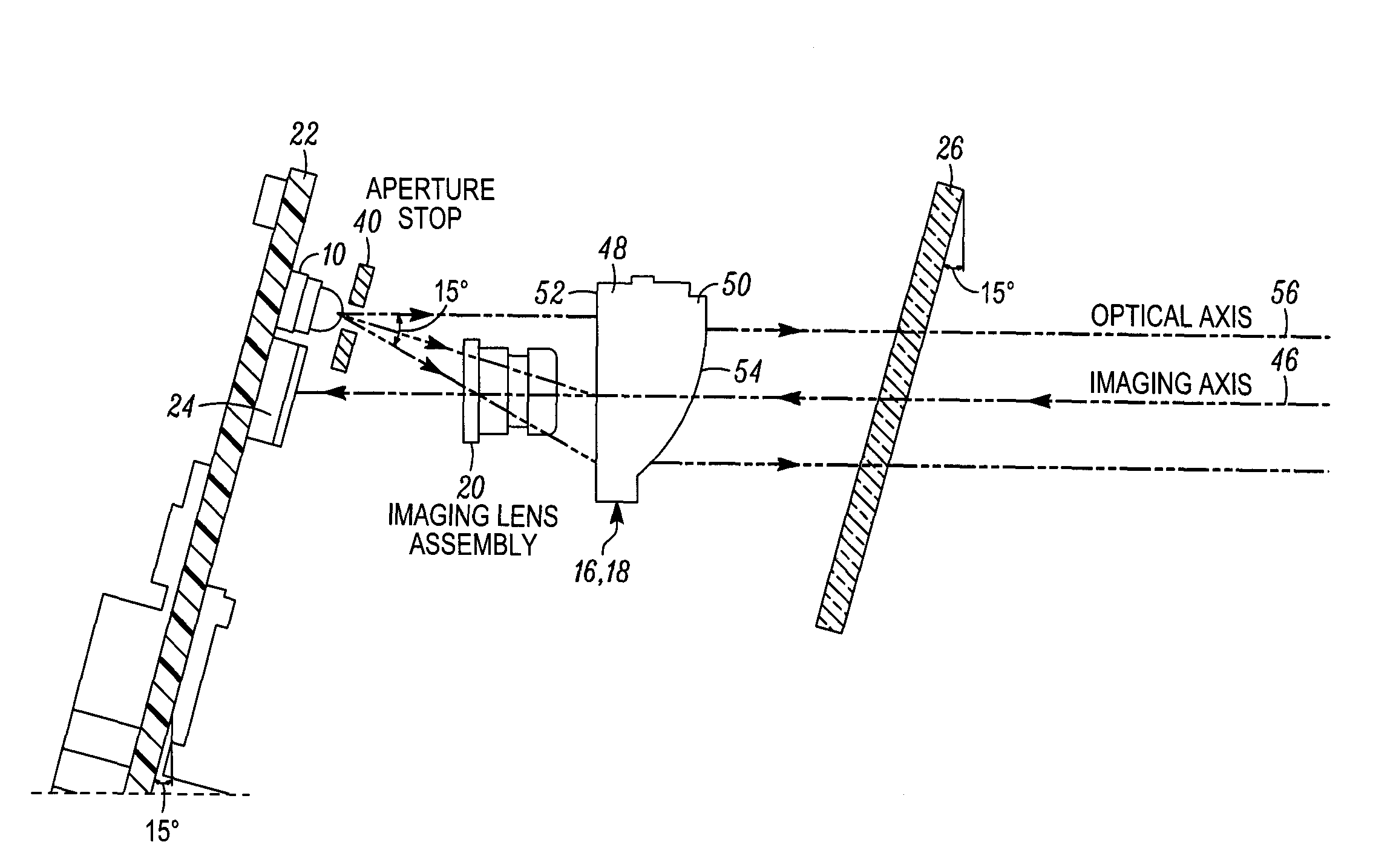
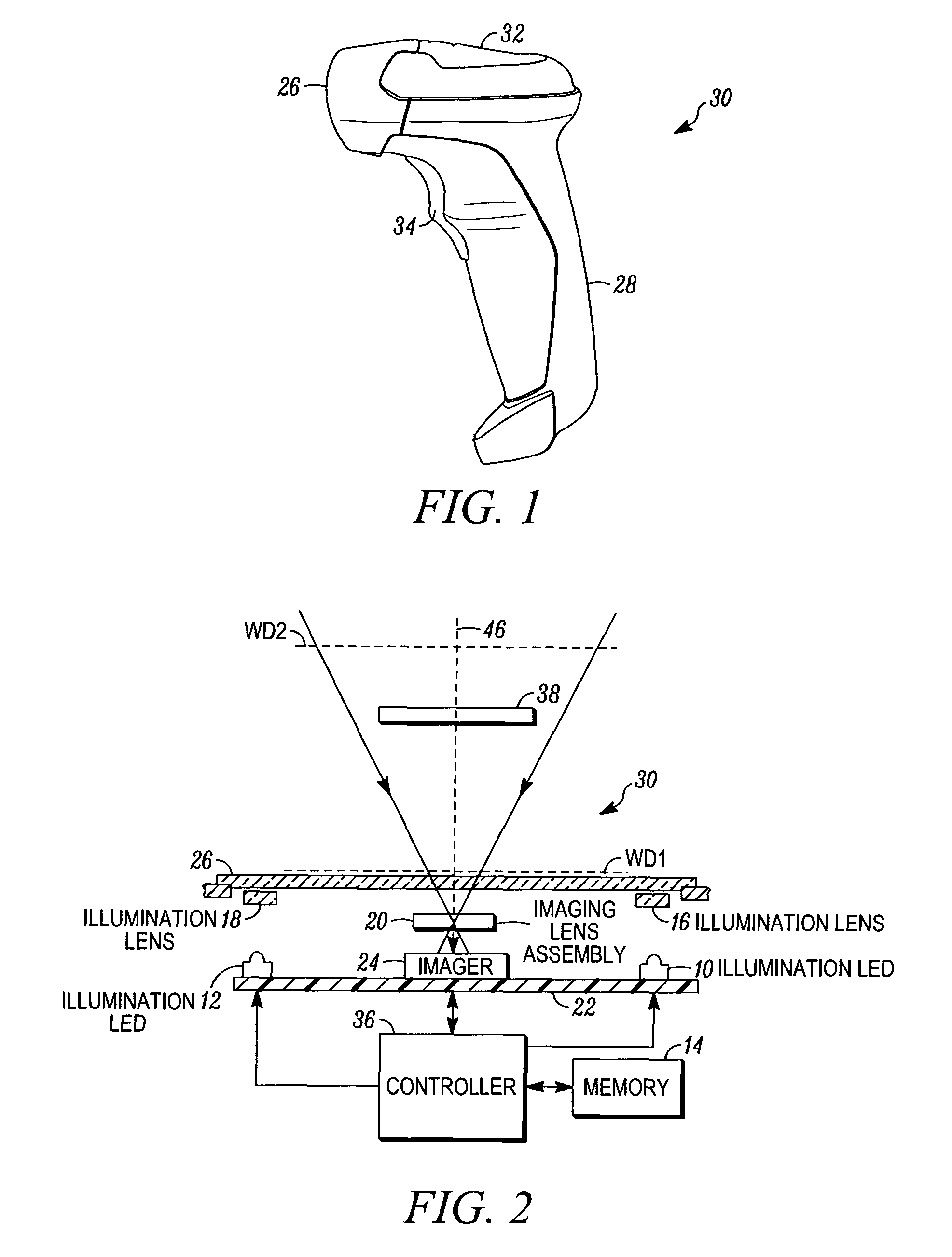
[0024]Reference numeral 30 in FIG. 1 generally identifies an ergonomic imaging reader configured as a gun-shaped housing having an upper barrel or body 32 and a lower handle 28 tilted rearwardly away from the body 32 at an angle of inclination, for example, fifteen degrees, relative to the vertical. A window 26 is located adjacent the front or nose of the body 32 and is preferably also tilted at an angle of inclination, for example, fifteen degrees, as best shown in FIG. 5, relative to the vertical. The imaging reader 30 is held in an operator's hand and used in a handheld mode in which a trigger 34 is manually depressed to initiate imaging of target indicia, especially one-dimensional symbols, to be read in a range of working distances relative to the window 26. Housings of other configurations can also be employed.

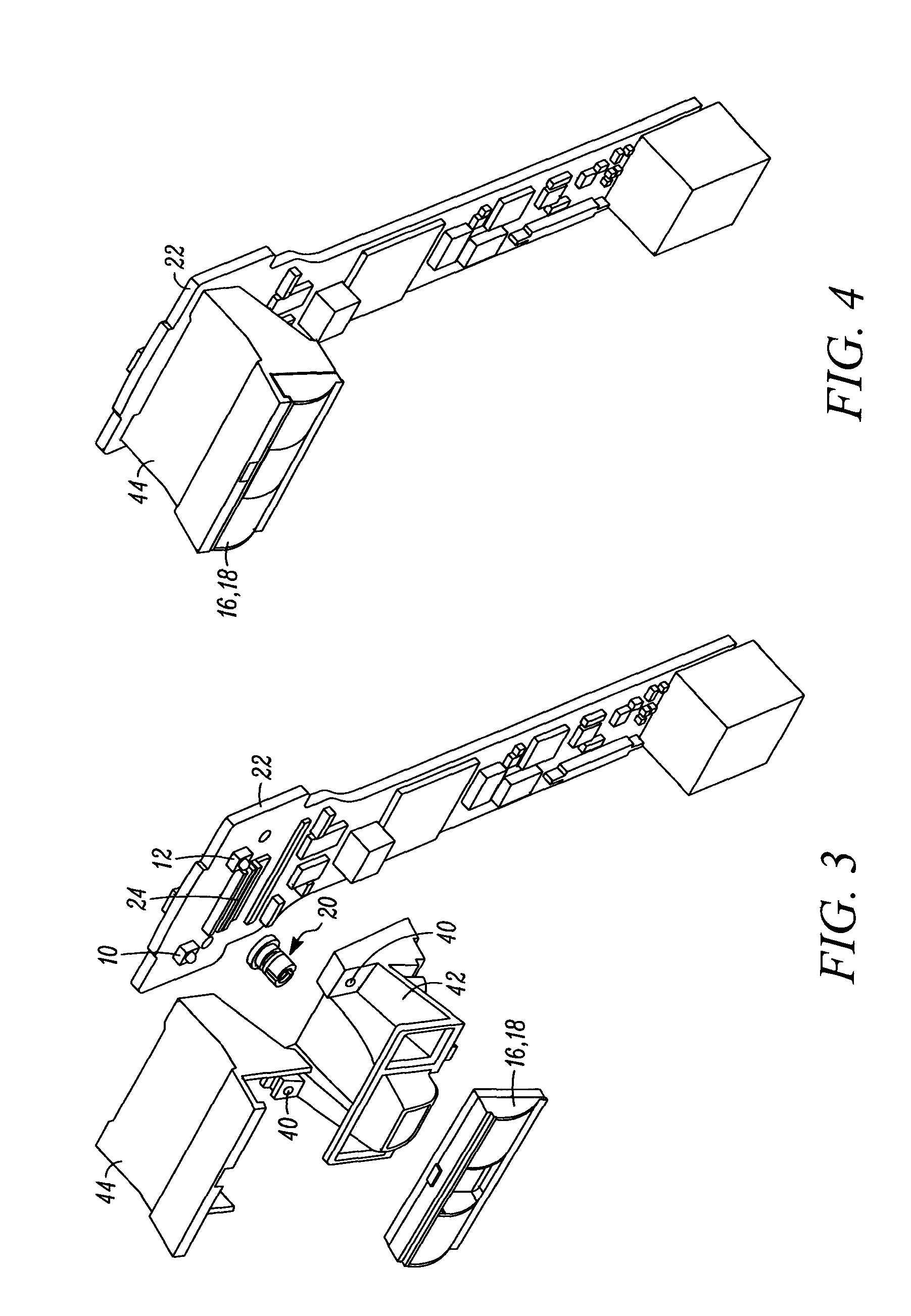
[0025]As schematically shown in FIG. 2, an imaging system or module includes an imager 24 mounted on a printed circuit board (PCB) 22 in the reader 30. The PCB 22 is mou...


PUM


Abstract

A substantially uniform distributed illumination pattern of light is generated on and along a symbol to be read by image capture. A solid-state imager is mounted on a tilted printed circuit board in a tilted handle of an ergonomic reader. An imaging lens assembly captures return light over a field of view from the symbol along an imaging axis, and projects the captured return light onto the imager. An illumination light source is mounted on the board for emitting illumination light at an acute angle of inclination relative to the imaging axis. An optical component includes a first lens portion with a polynomial incident surface for intercepting, bending and aligning the emitted illumination light to generate the pattern in a scan direction along the symbol, and a second lens portion with a toroidal or cylindrical aspherical surface for collimating the aligned illumination light to generate the pattern in a transverse direction.

Description

DESCRIPTION OF THE RELATED ART[0001]Solid-state imaging systems or imaging readers have been used, in both handheld and / or hands-free modes of operation, to electro-optically read targets, such as one-dimensional bar code symbols, particularly of the Universal Product Code (UPC) symbology having a row of bars and spaces spaced apart along a scan direction, as well as two-dimensional symbols, such as the Code 49 symbology having a plurality of vertically stacked rows of bar and space patterns in a single symbol, as described in U.S. Pat. No. 4,794,239.[0002]The handheld imaging reader includes a housing having a handle held by an operator, and an imaging module supported by the housing and aimed by the operator at the symbol during reading. The imaging module includes a solid-state imager with a sensor array of photocells or light sensors, which correspond to image elements or pixels in a field of view of the imager, and an imaging lens assembly for capturing return light scattered a...

Claims


Application Information

Patent Timeline
Patent Type & Authority Applications(United States)
IPC IPC(8): G06K7/10
CPCG06K7/10831G06K7/10732
Inventor LIU, RONGBARKAN, EDWARDDRZYMALA, MARKVINOGRADOV, IGOR
Owner SYMBOL TECH LLC
Why Eureka
Try Eureka