Light emitting device having plurality of light emitting cells and method of fabricating the same

Active Publication Date: 2011-12-08
SEOUL SEMICONDUCTOR
View PDF1 Cites 54 Cited by
  • Summary
  • Abstract
  • Description
  • Claims
  • Application Information

AI Technical Summary

Benefits of technology

[0048]According to the present invention, there can be provided a light emitting device having a plurality of light emitting cells, which can prevent electrical short circuits in the light emitting cells by preventing metallic etch byproducts from being produced, and allow current to be smoothly distributed in the light emitting cells by controlling a contact surface where an n-electrode is in contact with each of the light emitting cells. Further, according to the present invention, a reflective layer is not exposed

Problems solved by technology

Since the light emitting device has light emitting cells formed on a substrate used as a growth substrate, e.g., a sapphire substrate, the light emitting cells have a limitation in structure, and there is a limitation in improving light extraction efficiency.
When the first metal layer 31a comprises a reflective metal layer such as Ag or Al, such etching damage may be serious.
Since the surface of the metal layer 31a is damaged by plasma, the adhesion of the wires 57 or electrode pads formed on the metal layer 31a is lowered, resulting in a device failure.
However, etching damage may occur on the reflective metal layers that are

Method used


Image

  • Light emitting device having plurality of light emitting cells and method of fabricating the same
  • Light emitting device having plurality of light emitting cells and method of fabricating the same
  • Light emitting device having plurality of light emitting cells and method of fabricating the same

Examples


Embodiment Construction

[0055]Hereinafter, preferred embodiments of the present invention will be described in detail with reference to the accompanying drawings. The following embodiments are provided only for illustrative purposes so that those skilled in the art can fully understand the spirit of the present invention. Therefore, the present invention is not limited to the following embodiments but may be implemented in other forms. In the drawings, the widths, lengths, thicknesses and the like of elements may be exaggerated for convenience of illustration. Like reference numerals indicate like elements throughout the specification and drawings.

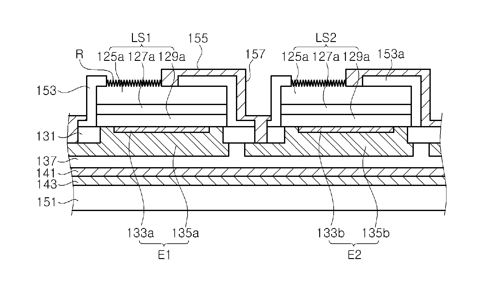
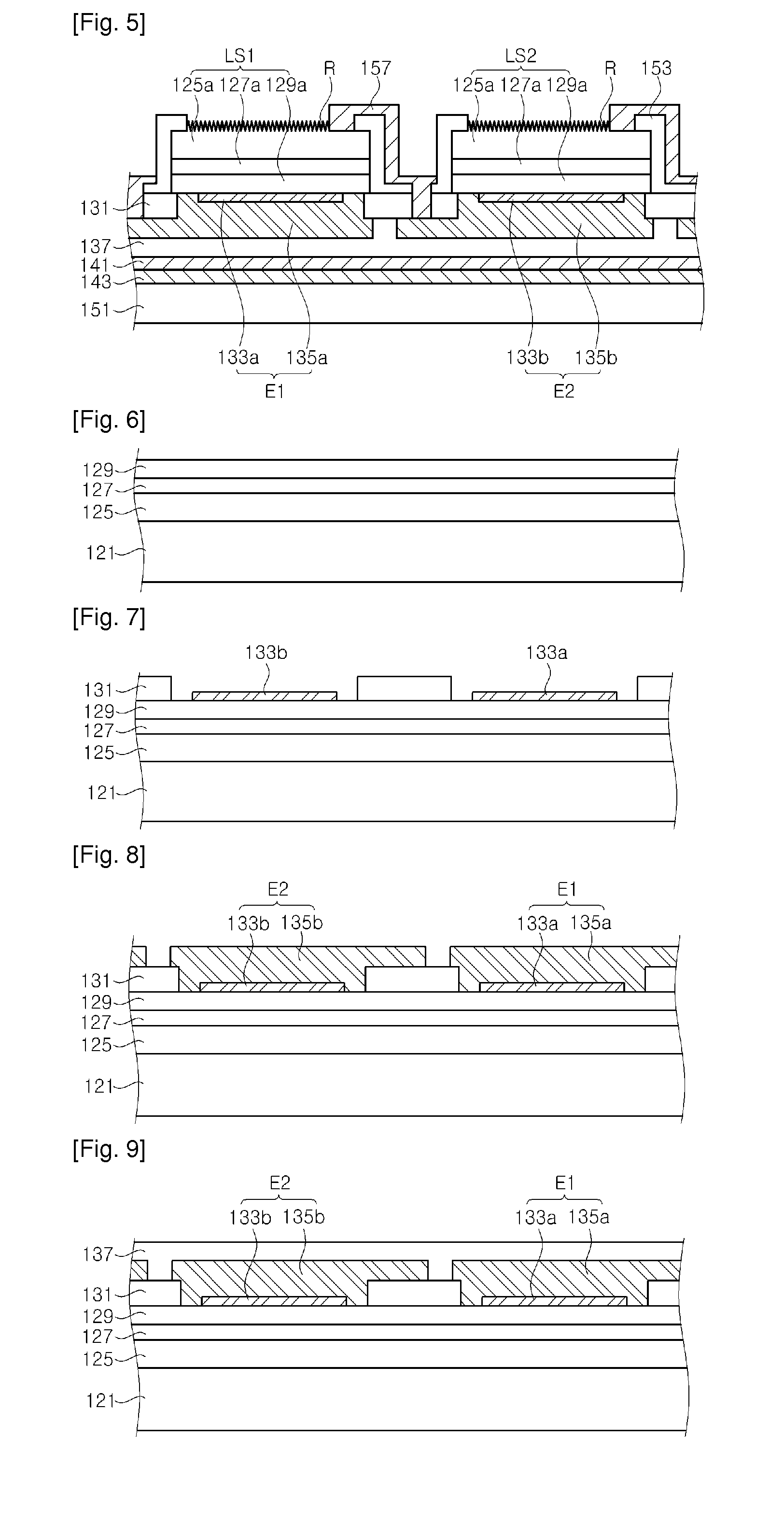
[0056]FIG. 5 is a sectional view illustrating a light emitting device having a plurality of light emitting cells according to an embodiment of the present invention.

[0057]Referring to FIG. 5, the light emitting device comprises a support substrate 151, a plurality of light emitting cells LS1 and LS2, wires 157, electrodes E1 and E2, an etching prevention layer 13...


PUM


Abstract

A light emitting device having a plurality of light emitting cells is disclosed. The light emitting device comprises a substrate; a plurality of light emitting cells positioned on the substrate to be spaced apart from one another, each of the light emitting cells comprising a p-type lower semiconductor layer, an active layer and an n-type upper semiconductor layer; p-electrodes positioned to be spaced apart from one another between the substrate and the light emitting cells, the respective p-electrodes being electrically connected to the corresponding lower semiconductor layers, each of the p-electrodes having an extension extending toward adjacent one of the light emitting cells; n-electrodes disposed on upper surfaces of the respective light emitting cells, wherein a contact surface of each of the n-electrodes electrically contacting with each light emitting cell exists both sides of any straight line that bisects the light emitting cell across the center of the upper surface of the light emitting cell; a side insulating layer for covering sides of the light emitting cells; and wires for connecting the p-electrodes and the n-electrodes, the wires being spaced apart from the sides of the light emitting cells by the side insulating layer.

Description

CROSS REFERENCE TO RELATED APPLICATIONS[0001]This application is the National Stage of International Application No. PCT / KR2010 / 001804, filed on Mar. 24, 2010, and claims priority from and the benefit of Korean Patent Application No. 10-2009-0027227, filed on Mar. 31, 2009, and Korean Patent Application No 10-2009-0027228, filed on Mar. 31, 2009, which are all hereby incorporated by reference for all purposes as if fully set forth herein.BACKGROUND OF THE INVENTION[0002]1. Field of the Invention[0003]The present invention relates to a light emitting device and a method of fabricating the same, and more particularly, to a light emitting device having a plurality of light is emitting cells having a vertical structure in which an n-electrode and a p-electrode are respectively formed on upper and lower portions of each light emitting cell.[0004]2. Discussion of the Background[0005]GaN-based light emitting diodes (LEDs) are widely used for display and backlights. Further, LEDs have less ...

Claims


Application Information

Patent Timeline
IPC IPC(8): H01L33/62
CPCH01L25/0753H01L27/153H01L33/0079H01L33/38H01L2224/92247H01L33/641H01L2933/0016H01L2224/73265H01L33/405H01L33/0093
Inventor SEO, WON CHEOLKAL, DAE SUNGLEE, JOON HEEKIM, CHANG YOUN
Owner SEOUL SEMICONDUCTOR
Why Eureka
Try Eureka