Package manufacturing method, piezoelectric vibrator manufacturing method, oscillator, electronic device and radio timepiece
Inactive Publication Date: 2011-12-15
SII CRYSTAL TECH +1
View PDF5 Cites 0 Cited by
Summary
Abstract
Description
Claims
Application Information
AI Technical Summary
This helps you quickly interpret patents by identifying the three key elements:
Problems solved by technology
Method used
Benefits of technology
Benefits of technology
[0016]In the invention, the cooling rate from the strain point of the glass material that forms the through electrode forming substrate wafer plus 50° C. to the strain point minus 50° C. is made slower than the cooling rate from the heating temperature of the welding step to the strain point plus 50° C. In the welding step, the through electrode forming substrate wafer is heated to the softening point that is higher than the strain point. Therefore, if rapid cooling is performed in the cooling step, there is a possibility that strain remains in the through electrode forming substrate wafer. To address this, by reducing the cooling rate in a range of plus / minus 50° C. of the strain point, it is possible to inhibit generation of strain in the through electrode forming substrate wafer.
[0035]According to the invention, the through electrode forming substrate wafer is welded to the core portion by heating the through electrode forming substrate wafer while it is pressed by the pressurizing die. Therefore, it is possible to inhibit recessed portions, which could cause disconnection in an electrode film forming step, from being generated around the through electrodes. Further, it is possible to ensure stable conductivity between the piezoelectric vibrating reed and external electrodes, and it is also possible to ensure stable airtightness in the cavity of the piezoelectric vibrator. Therefore, uniform performance of the piezoelectric vibrator can be achieved.
Problems solved by technology
However, the volume of the through electrode formed by the silver paste reduces when organic material, such as resin in the silver paste, is removed by firing.
Then, there are cases in which the recessed portion or hole of the through electrode causes deterioration of airtightness in the cavity or degradation of conductivity between the piezoelectric vibrating reed and the external electrodes.
However, since an organic binder contained in the glass frit is removed by firing, there are cases in which a recessed portion is generated in the surface of the glass frit due to volume reduction.
Method used
Image
Click on the blue label to locate the original text in one second.
Reading with bidirectional positioning of images and text.
Examples
first embodiment
[0065]Hereinafter, a package manufacturing method according to a first embodiment of the invention will be described based on FIG. 1 to FIG. 7D.
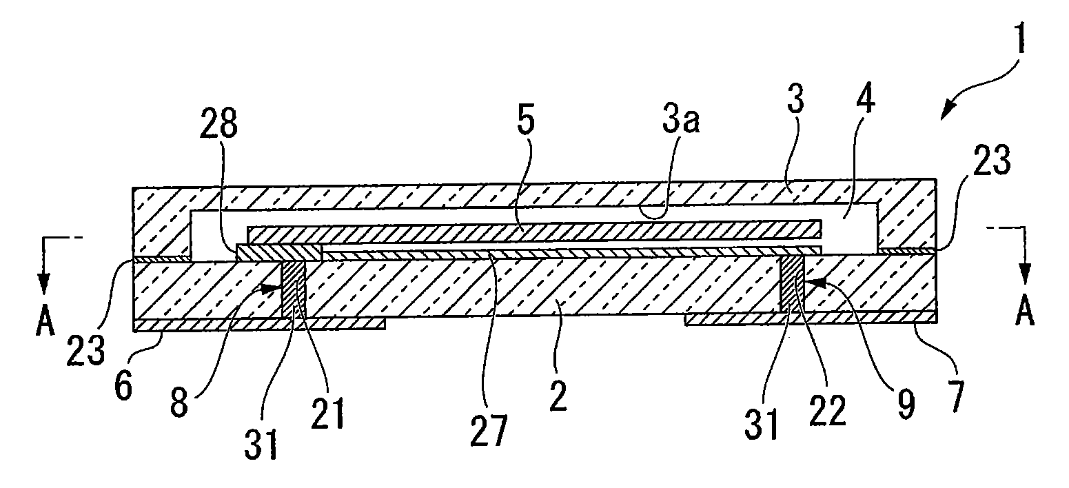
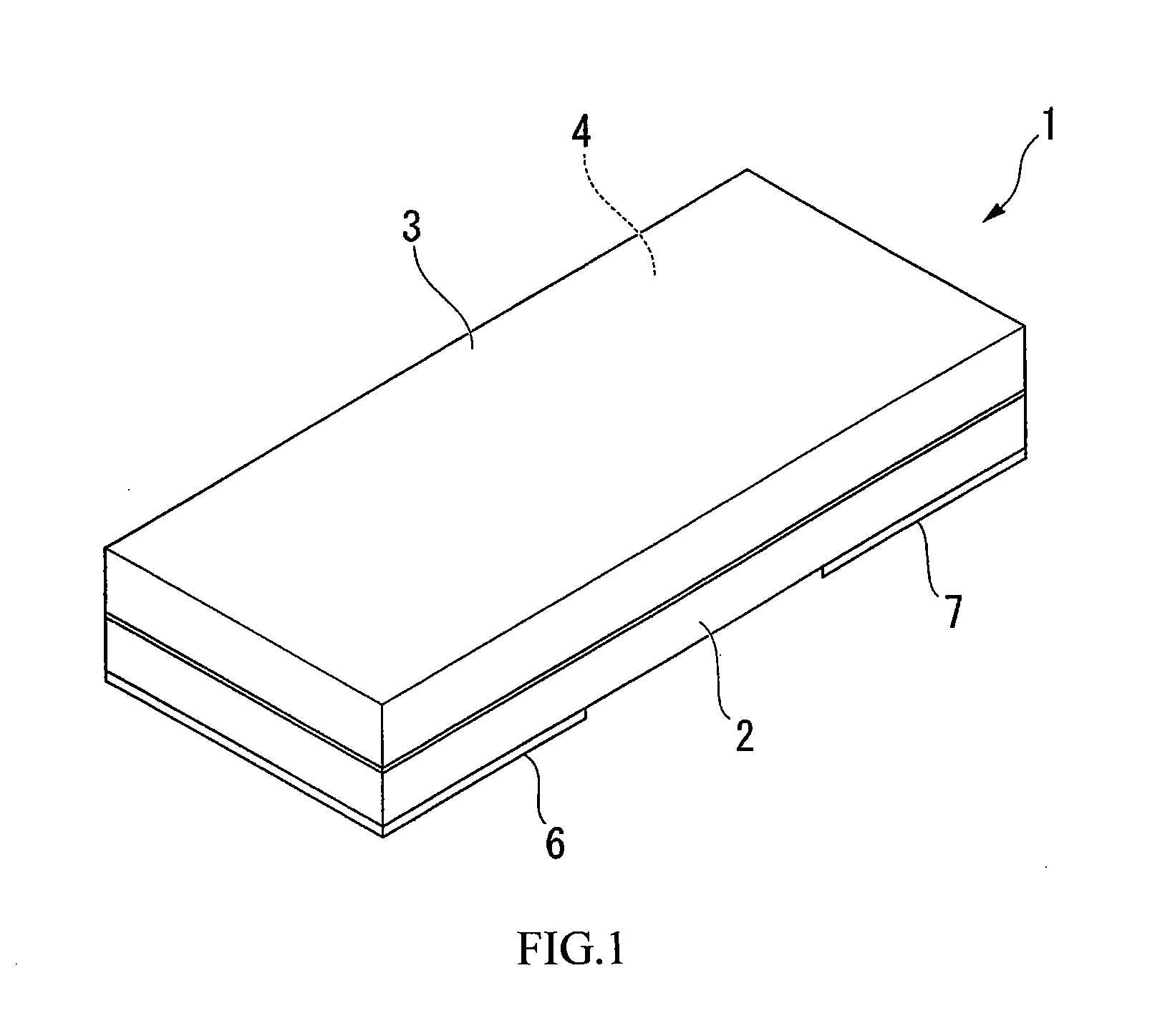
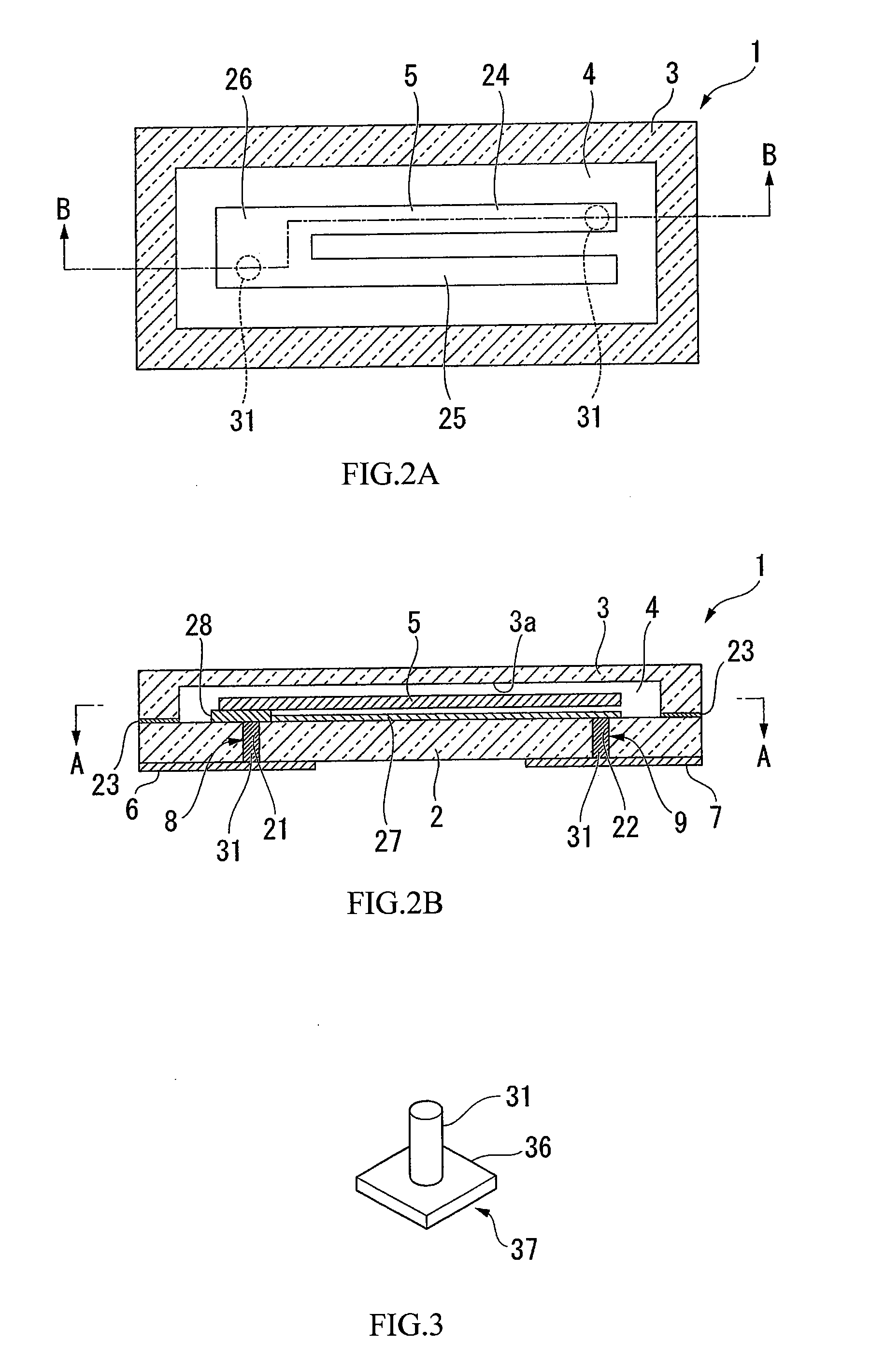
[0066]As shown in FIG. 1, FIG. 2A and FIG. 2B, a piezoelectric vibrator 1 according to the first embodiment is formed in a box shape such that a base substrate 2 and a lid substrate 3 are laminated in two layers, and is the surface mount type piezoelectric vibrator 1 in which a piezoelectric vibrating reed 5 is housed in an internal cavity 4. The piezoelectric vibrating reed 5 and external electrodes 6, 7 that are arranged on the outside of the base substrate 2 are electrically connected by a pair of through electrodes 8, 9 that penetrate the base substrate 2.
[0067]The base substrate 2 is a transparent insulating substrate made of a glass material, such as soda lime glass for example, and is formed in a plate shape. A pair of through holes 21, 22, in which the pair of through electrodes 8, 9 are formed, are formed in the base substrate 2.
[00...
second embodiment
[0132]Next, a package manufacturing method according to a second embodiment of the invention will be described based on FIG. 8 to FIG. 12. Members and portions that are the same or similar to those of the above-described first embodiment are denoted with the same reference numerals and a description thereof is omitted. A structure that differs from that of the first embodiment will be described.
[0133]As shown in FIG. 8, in a piezoelectric vibrator 201 according to the second embodiment, core portions 231 that become the through electrodes 8, 9 are formed in a truncated cone shape, and inner peripheral surfaces of through holes 221, 222 are tapered surfaces.
[0134]As shown in FIG. 9, each of the core portions 231 forms a rivet 237 together with a base portion 236 in a manufacturing process, in a similar manner to the first embodiment.
[0135]In the manufacturing process, the through holes 221, 222 are first formed in the base substrate wafer 41 as recessed portions (hole portions) 221a,...
modified examples
[0159]Next, modified examples of the above-described embodiments will be described based on FIG. 13A to FIG. 15. Members and portions that are the same or similar to those of the above-described embodiments are denoted with the same reference numerals and a description thereof is omitted. Structures that differ from those of the embodiments will be described.
[0160]As shown in FIG. 13A and FIG. 13B, in a package manufacturing method according to a modified example of the first embodiment, core portions 75 that form the through electrodes 8, 9 are column-shaped metal pins having a thickness thicker than that of the base substrate wafer 41 in a manufacturing process. The core portions 75 are not connected to base portions.
[0161]As shown in FIG. 13A, a receiving die 62b that holds the base substrate wafer 41, in which the core portions 75 are inserted in the through holes 21, 22, includes a receiving die flat plate portion 65b and recessed portions 66b corresponding to the tip ends of t...
PUM
Property
Measurement
Unit
Temperature
aaaaa
aaaaa
Temperature
aaaaa
aaaaa
Time
aaaaa
aaaaa
Abstract
Provided is a manufacturing method of a package including a plurality of substrates that are bonded to each other, a cavity that is formed inside the plurality of substrates, and through electrodes that conduct current between the inside of the cavity and the outside of the plurality of substrates. The through electrodes are each formed such that a conductive core portion made of a metal material is arranged in a hole portion of a through electrode forming substrate made of a glass material. The manufacturing method includes: a hole portion forming step of forming the hole portion, into which the core portion is inserted, in a through electrode forming substrate wafer; a core portion inserting step of inserting the core portion into the hole portion formed in the through electrode forming substrate wafer; a welding step of heating the through electrode forming substrate wafer and welding it to the core portion; and a cooling step of cooling the through electrode forming substrate wafer. In the welding step, the through electrode forming substrate wafer is welded to the core portion by heating the through electrode forming substrate wafer to a temperature higher than a softening point of the glass material while a pressurizing die is placed on a surface of the through electrode forming substrate wafer and the through electrode forming substrate wafer is pressed by the pressurizing die.
Description
RELATED APPLICATIONS[0001]This application is a continuation of PCT / JP2010 / 052456 filed on Feb. 18, 2010, which claims priority to PCT / JP2009 / 053328 filed on Feb. 25, 2009. The entire contents of these applications are incorporated herein by reference.BACKGROUND OF THE INVENTION[0002]1. Field of the Invention[0003]The present invention relates to: a manufacturing method of a package including a plurality of substrates that are bonded to each other, a cavity that is formed inside the plurality of substrates, and through electrodes that conduct current between the inside of the cavity and the outside of the plurality of substrates; a piezoelectric vibrator in which a piezoelectric vibrating reed is mounted on the through electrodes and is disposed inside the cavity; an oscillator having the piezoelectric vibrator; an electronic device; and a radio timepiece.[0004]2. Description of the Related Art[0005]In recent years, mobile telephones and portable information terminal devices employ ...
Claims
Application Information
Patent Timeline
Application Date:The date an application was filed.
Publication Date:The date a patent or application was officially published.
First Publication Date:The earliest publication date of a patent with the same application number.
Issue Date:Publication date of the patent grant document.
PCT Entry Date:The Entry date of PCT National Phase.
Estimated Expiry Date:The statutory expiry date of a patent right according to the Patent Law, and it is the longest term of protection that the patent right can achieve without the termination of the patent right due to other reasons(Term extension factor has been taken into account ).
Invalid Date:Actual expiry date is based on effective date or publication date of legal transaction data of invalid patent.

