Device and method for regulating pressure in a heart chamber

a technology of a heart chamber and a device, applied in the field of devices and methods for regulating pressure in the heart chamber, can solve the problems of reduced cardiac output, increased cardiac filling pressure, fluid accumulation, etc., and achieve the effect of accurate compensation

Active Publication Date: 2011-12-15
WAVE LTD V
View PDF9 Cites 126 Cited by
  • Summary
  • Abstract
  • Description
  • Claims
  • Application Information

AI Technical Summary

Benefits of technology

[0027]The present invention successfully addresses the shortcomings of the presently known configurations by providing a device which can more accurately compensate for a disordered hemodynamic state of a heart of a CHF patient and which can be implanted using minimally invasive approaches.

Problems solved by technology

Such weakening or stiffening leads to reduced cardiac output, an increase in cardiac filling pressures, and fluid accumulation.
This impedes blood filling into the heart and produces backup into the lungs resulting in pulmonary venous hypertension and lung edema.
Mechanical devices enable propulsion of significant amounts of blood (liters / min) but are limited by a need for a power supply, relatively large pumps and possibility of hemolysis and infection are all of concern.
Surgical approaches such as dynamic cardiomyoplasty or the Batista partial left ventriculectomy are used in severe cases, as is heart transplantation, although the latter is highly invasive and limited by the availability of donor hearts.

Method used


Image

  • Device and method for regulating pressure in a heart chamber
  • Device and method for regulating pressure in a heart chamber
  • Device and method for regulating pressure in a heart chamber

Examples


example 1

Flow Calculations

[0109]The present inventors have calculated the flow needed to reduce left atrial pressure (LAP) to below 25 mmHg. For the purpose of calculations it was assumed that under SHF and DHF, the LAP minimum and maximum pressures are the same (12 mmHg & 28 mmHg respectively). In order to treat these conditions, LAP must be reduced by 3-5 mmHg.

[0110]The following parameters were taken into consideration:

[0111](i) SHF cardiac output (CO)=2.5-4 l / min heart rate (HR)=75 (ii) DHF CO=3-5.5 l / min HR=70. In SHF one can assume a linear correlation between LA pressure and volume (Pstatic fluid=ρgh), and thus one can calculate the following:

[0112]In SHF: LAP-16 mmHg, Filling volume-50 cc each cycle. Reducing LAP by 3-5 mmHg i.e. 3-5 / 16=20%-30% requires 20%-30% less blood i.e. 10 cc-16 cc of blood each heart beat which translates to ˜0.75 l / min to 1.2 l / min LA-RA flow in SHF [10 cc & 16 cc×75 (HR)]

[0113]To find an optimal shunt diameter, one can use Bernouli's equation and assume no ...

example 2

Construction and Deployment of One Embodiment of the Present Device

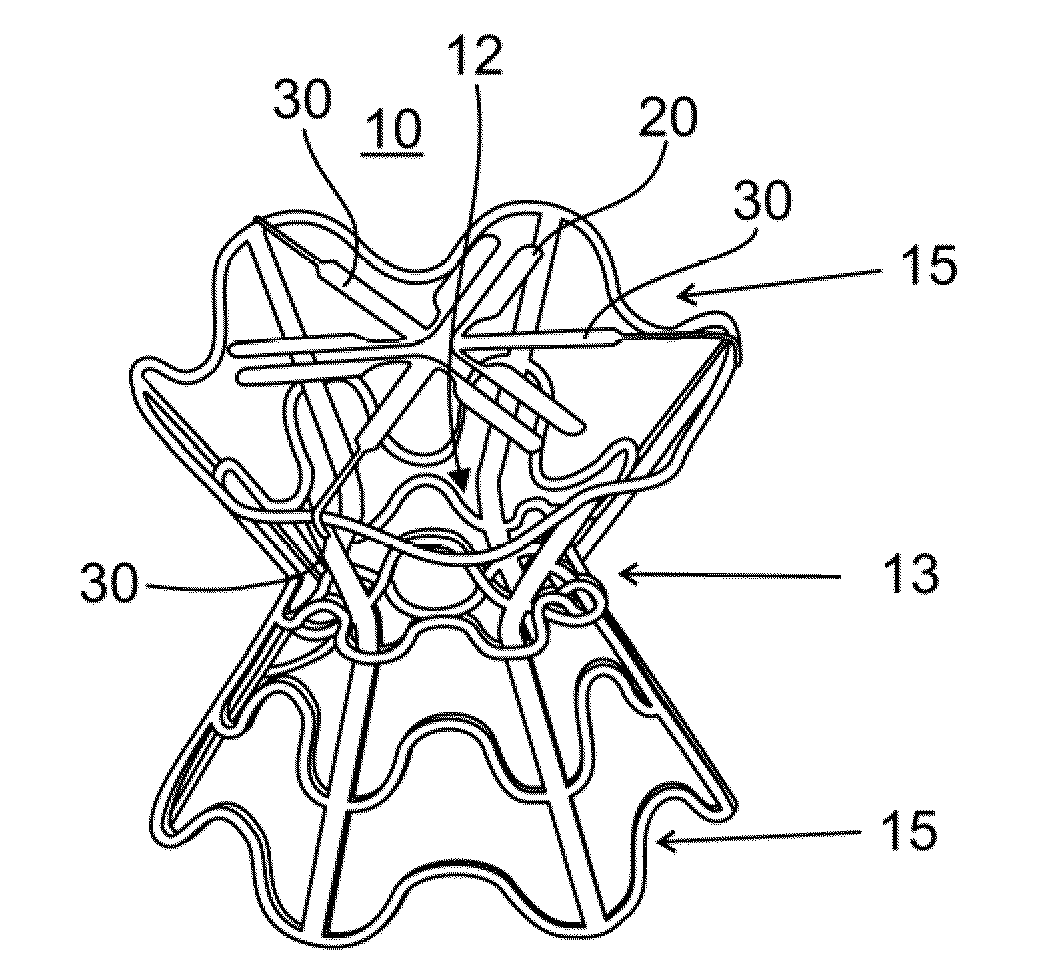
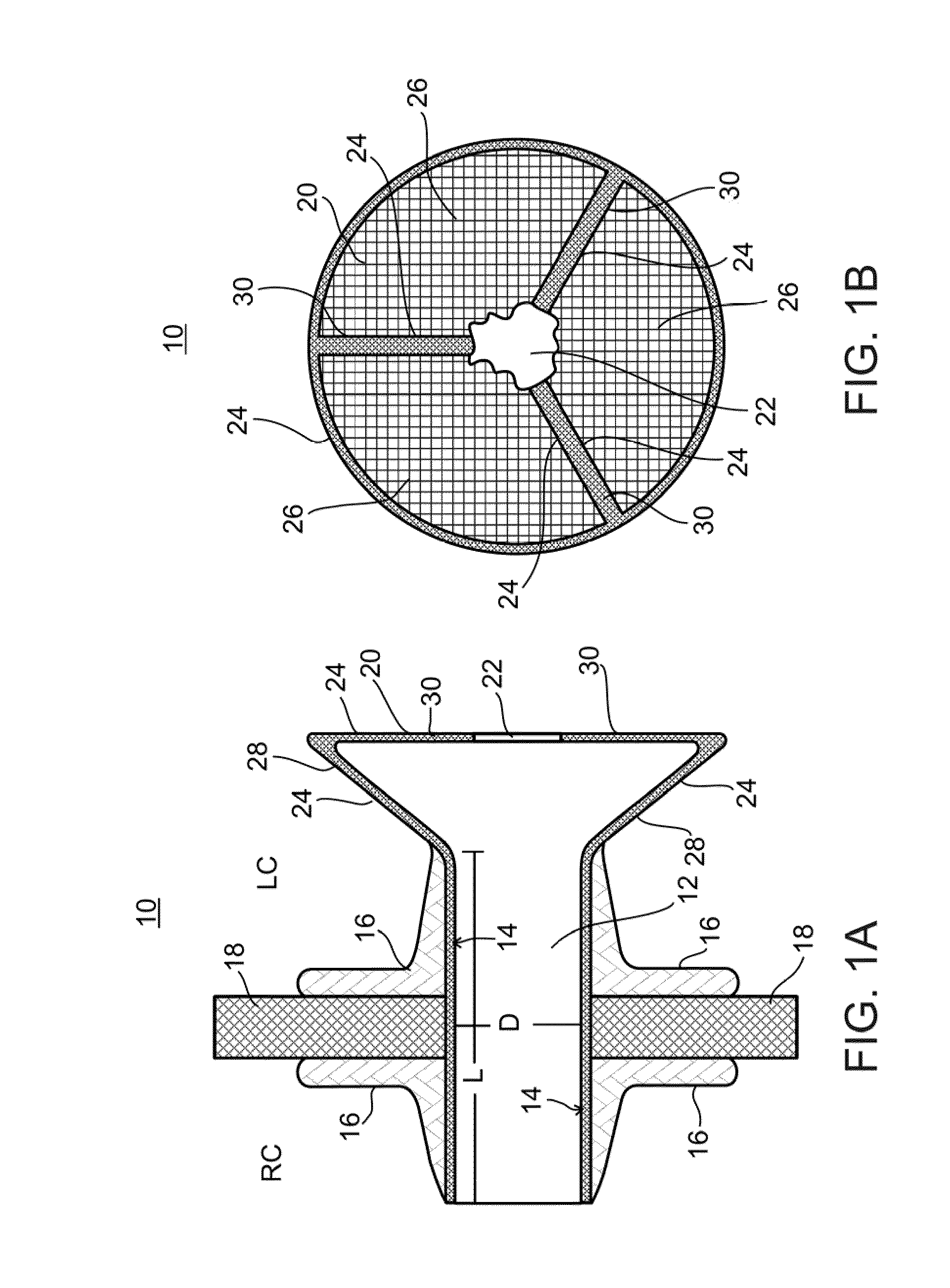
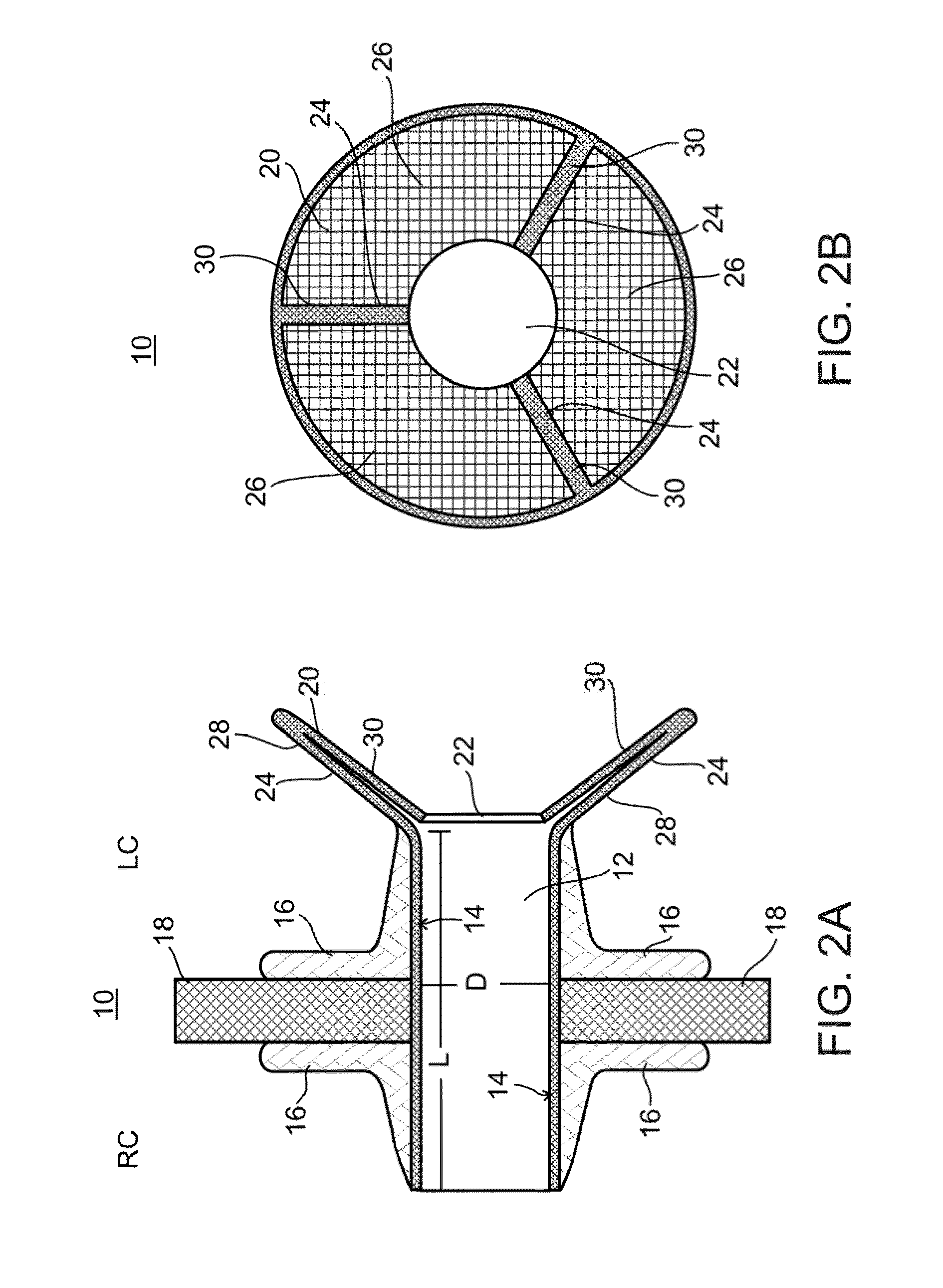
[0120]A device similar to the one illustrated in FIGS. 1A-2B is manufactured as follows. A NITINOL tube having a diameter of 5 mm, a length of 18 mm and a wall thickness of 0.25 mm is laser cut to create a tubular wire frame. The tubular frame is electro-polished and cleaned and then heat treated to set its final shape on a mandrel. The internal and external surfaces of the frame are wrapped with ePTFE. Valve leaflets are die cut from 0.25 mm thick bovine pericardium tissue and sutured to form a partially open leaflet valve which is then sutured onto the tubular frame over the fabric at the funnel opening. The resultant device is packed until use under sterile conditions. Prior to transplantation, the device is unpacked and collapsed by hand or by a crimping tool to a final diameter of less than 13 F. the collapsed device is loaded into a catheter and placed in front of a pusher rod fitted into the catheter. The devi...

example 3

Construction and Testing of a Diabolo-Shaped Device

[0121]A diabolo-shaped configuration of the present device was constructed by laser cutting a stent from Nitinol tubing and shaping the cut stent into a Diabolo by using a mandrel and applying 530° C. for 12 minutes. Bars for forming the valve arms were laser cut from a 0.0.09 mm thick Nitinol sheet and the bars were shaped using a mandrel. The shaped bars were then welded to the diabolo-shaped stent at three points encircling an opening of the stent. The bare wire frame form of the device is shown in FIG. 6A.

[0122]The stent was then covered with ePTFE impregnated with carbon and Pericard leaflets were sutured to the three bars and the circumference of the stent around the three bars (FIG. 6B). The finished device was then sterilized and collapsed for loading into a sheath.

[0123]The device shown in FIG. 6B was tested using the flow chamber described below to simulate the fluid pressures present in heart chambers. The device performe...


PUM


Abstract

A device for regulating blood pressure in a heart chamber is provided. The device includes a shunt positionable within a septum of the heart. The shunt is designed for enabling blood flow between a left heart chamber and a right heart chamber, wherein the flow rate capacity of the device is mostly a function of pressure in the left heart chamber.

Description

CROSS-REFERENCE TO RELATED APPLICATIONS[0001]This application is a continuation under 35 U.S.C. §120 of International Patent Application No. PCT / IL2010 / 000354, filed May 4, 2010 and entitled “Device and Method for Regulating Pressure in a Heart Chamber,” which claims the benefit of U.S. Provisional Patent Application No. 61 / 175,073, filed May 4, 2009, and U.S. Provisional Patent Application No. 61 / 240,667, filed Sep. 9, 2009, the entire contents of each of which are incorporated by reference herein.FIELD[0002]The present invention relates to a device which can be used to regulate pressure in a heart chamber. Specifically, the present invention relates to a device which can be used to lower a blood pressure in a left atrium in response to an increase in left atrial pressure and to a method of utilizing such a device in treatment of congestive heart failure related conditions such as Pulmonary Edema and decompensated heart failure caused by elevated pressures in a left side chamber of...

Claims


Application Information

Patent Timeline
Patent Type & Authority Applications(United States)
IPC IPC(8): A61M1/00
CPCA61F2/2418A61M27/002A61M27/006A61F2220/0058A61F2002/249A61F2230/0013A61F2230/0078A61F2/2412A61F2220/0066
Inventor NITZAN, YAACOVHARARI, BOAZSHMULEWITZ, ASCHERSIVAN, TOVY
Owner WAVE LTD V
Why Eureka
Try Eureka